Advertisement
Quick Links
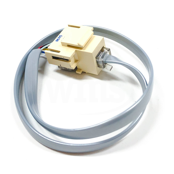
MMI Extension Cable
Product Description
The MMI Extension Cable (Figure 1) is an accessory
that allows you to connect a computer to an Open
Processor, Controller Module, or Gateway Module
and use the computer when the enclosure door is
closed or locked. The cable can be used with a
Modular Building Controller (MBC), Remote Building
Controller (RBC), or the Controller Board of a Floor
Level Network (FLN) Controller.
NOTE: See the following manuals for further
information about system installation and
programming constraints:
• Smoke Control Application and
Engineering Manual (125-1806)
• APOGEE Automation Technical
Reference on InfoLink
Product Numbers
545-712
MMI Extension Cable Assembly
(includes RJ-11 plug and RJ-11 jack)
Required Tools
• Flat-blade screwdriver
Figure 1. MMI Extension Cable.
Item Number: 545-407-04, Rev. 010
Installation Instructions
Expected Installation Time
3 minutes
Prerequisites
• None
Installation
1.
Use a screwdriver to tap on the MMI extension
cable knockout until it is removed.
See Figure 2 for an MBC/RBC enclosure, or
Figure 3 for an FLN Controller enclosure.
2.
Insert the RJ-11 jack of the extension cable
(Figure 1) into the knockout and snap the jack
in place.
Figure 2. Installing an Extension Cable (MBC/RBC).
WARNING: Risk of static discharge.
Underwriters Laboratories Inc.
®
¤
LISTED
C
¤
Turn OFF power before removing or servicing
boards. Use ESD wrist strap when servicing unit.
SMOKE CONTROL SYSTEM EQUIPMENT SUBASSEMBLY.
Controller Board
Also suitable for use as:
ENERGY MANAGEMENT SUBASSEMBLY.
BLN #
Field Panel No./Name
Also suitable for use as:
SIGNAL SYSTEM UNIT SUBASSEMBLY.
Also suitable for use as:
PROCESS MANAGEMENT EQUIPMENT SUBASSEMBLY.
Issue No.
BPS (Bits per second)
For use with System 600 as part of an engineered
MMI
smoke control system in accordance with NFPA 92A.
FLN1
Modem
FLN2
MMI
WARNING:
Power must be ON
FLN3
BLN
when replacing the
battery, otherwise
the cabinet will
Product Part No.
545-793
coldstart.
Refer to Installation Instructions, Part No.
545-429
+
-
S
+
-
S
+
-
S
+
-
S
F
F
F
L
L
L
B
N
N
N
L
1
2
3
N
Figure 3. Installing an Extension Cable
(FLN Controller).
Document No. 545-407
February 7, 2003
RJ-11
PLUG
MMI
Port
MMI
Memory
Modem
Port
VDC
TIU
Enabled
RJ-11
KNOCKOUT
PLUG
Page 1 of 2
12
Advertisement

Subscribe to Our Youtube Channel
Related Manuals for Siemens MMI


Summary of Contents for Siemens MMI
- Page 1 MMI Extension Cable Expected Installation Time Product Description 3 minutes The MMI Extension Cable (Figure 1) is an accessory that allows you to connect a computer to an Open Prerequisites Processor, Controller Module, or Gateway Module and use the computer when the enclosure door is •...
- Page 2 Insert the RJ-11 plug of the extension cable Insert the RJ-11 plug of the extension cable into the MMI port on the right side of the Open into the MMI port located on the right side of Processor or Controller Module (Figure 4 and the installed Controller Board (Figure 6).
Need help?
Do you have a question about the MMI and is the answer not in the manual?
Questions and answers