Table of Contents
Advertisement
Advertisement
Table of Contents

Related Manuals for Danfoss DHP-AQ Series


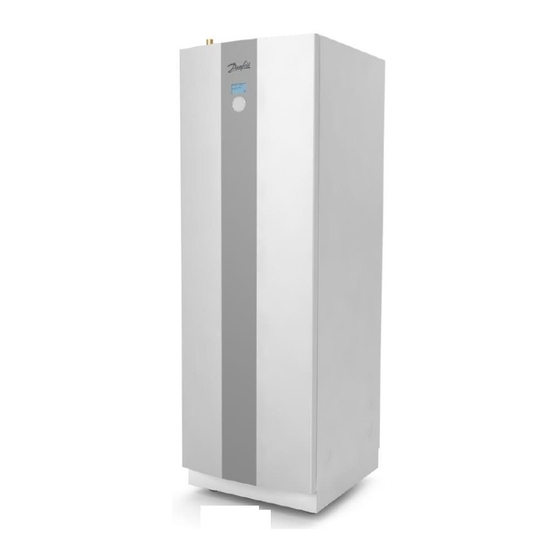
Summary of Contents for Danfoss DHP-AQ Series
- Page 1 MAKING MODERN LIVING POSSIBLE Service Instructions DHP-AQ www.heating.danfoss.com...
- Page 2 Danfoss A/S is not liable or bound by warranty if these instructions are not adhered to during installation or service. The English language is used for the original instructions. Other languages are a translation of the original instructions. (Directive 2006/42/EC)
-
Page 3: Table Of Contents
Operational problems ............Danfoss Heating Solutions... -
Page 4: About Documents And Decals
Information regarding making the handling of the installation easier or a possible operational technical disad- vantage. Symbols on decals The following symbols can occur on decals on the different parts of the heat pump. Which symbols are used depends on the heat pump model. VMGFJ202 Danfoss Heating Solutions... - Page 5 Component, accessorie according to proposed system sol- utions Supply line sensor Return line sensor 1.3.3 Pipe connections Tap water Heating system Brine system Defrosting tank Expansion tank with safety valve, brine Air bleeding Temperature and pressure relief valve Outdoor unit Water heater Danfoss Heating Solutions VMGFJ202...
-
Page 6: Important Information/Safety Regulation
Bleed valves must be installed where necessary. Caution The hot water tank must be equipped with an approved safety valve. Caution Heating systems with closed expansion tanks must also be supplied with approved pressure gauges and safe- Caution ty valves. VMGFJ202 Danfoss Heating Solutions... -
Page 7: Refrigerant
Risk of personal injury! Refrigerant exposed to a naked flame creates a poisonous irritating gas. This gas can Warning be detected by its odour even at concentrations below its permitted levels. Evacuate the area until it has been sufficiently ventilated. Danfoss Heating Solutions VMGFJ202... -
Page 8: Electrical Connection
Draining and refilling must only be carried out using new refrigerant (for the amount and type of refrigerant see manufacturer’s plate) through the service valves. All warranties from Danfoss are void if, when filling with refrigerant other than Danfoss A/S specified refriger- Caution ant, if there has not been written notification that the new refrigerant is an approved replacement refrigerant together with other remedies. -
Page 9: Commissioning
If the installation is only to be driven by the immersion heater during the installation, ensure that the heating Caution system is filled and the brine pump and compressor cannot be started. This is carried out by setting the oper- ating mode to AUX. HEATER. Danfoss Heating Solutions VMGFJ202... -
Page 10: Troubleshooting
Sensor fault alternatively cable fault. POOL SENSOR Sensor fault alternatively cable fault. COM. ERROR HP-CARD Communication broken between display card and heat pump card (outdoor). COM. ERROR HUB-CARD Communication broken between display card and hub card (indoor). VMGFJ202 Danfoss Heating Solutions... -
Page 11: Components
Hot water will stop to indicate that something noteworthy has occurred. Components 3.2.1 Outdoor unit Fig. 1: Components Position Name Position Name Electrical cabinet Electronic expansion valve Receiver Pressure transmitter Drying filter Suction line Heat exchanger Compressor Flow sensor High pressure switch Heating system supply line Danfoss Heating Solutions VMGFJ202... -
Page 12: Measurement Points
When reading the resistance of the sensors, the sensor leads must first be disconnected from the control equipment. °C Outdoor / Defrost sensor PT1000 sensor Other sensors 150 ohm, Ω 1000 ohm, Ω 22 kilo ohm, kΩ 1884 – – 1443 – – VMGFJ202 Danfoss Heating Solutions... - Page 13 1. Disconnect the relevant sensor from I/O-card/terminal block. 2. Measure the resistance for the sensor and any extension cables. 3. Then measure the sensor only. To ensure the sensor value the actual temperature must be checked against the measured resistance. Danfoss Heating Solutions VMGFJ202...
-
Page 14: Check Points
Installation instructions. DHP-AQ Midi Check points Temperatures Condensing temperature: 0.5 – 1.5 °C above supply line temperature Evaporation temperature: 7 - 8 °C Radiator circuit: 8°K temperature difference Overheating R407C: 4K ±1 K VMGFJ202 Danfoss Heating Solutions... -
Page 15: Operational Problems
If there appears to be a leak in the refriger- ant circuit, carry out leak tracing and any necessary corrective action. Danfoss Heating Solutions VMGFJ202... - Page 16 See marking. ▪ Pressure switch fault, opens at a higher pressure than indicated (mark pressure). Check using the manome- ter apparatus. ▪ Defective pressure switch, never opens. VMGFJ202 Danfoss Heating Solutions...
- Page 17 If there appears to be a leak in the refriger- ant circuit, carry out leak tracing and any necessary corrective action. Danfoss Heating Solutions VMGFJ202...
- Page 18 (not is started. just warm) even a distance from the compressor. ▪ When the compressor runs with the phases incorrect- ly sequenced a strange noise may be heard (loud, rat- tling) when the compressor runs backwards. VMGFJ202 Danfoss Heating Solutions...
- Page 19 Try cutting the voltage to the heat pump to stop the alarm and then manually run the circulation pump.If the alarm recurs, repeat the procedure several times. If this does not help, replace the circulation pump. Danfoss Heating Solutions VMGFJ202...
- Page 20 Try closing the filler valve and see if water coming cold water and valve on the expansion vessel on the hot side. stops dripping from the safety valve. If not, heating system not closed replace the filler valve. or leaking. VMGFJ202 Danfoss Heating Solutions...
- Page 21 ▪ Establish when clicking occurs, during heating and/or Try lubricating lead-ins in walls, ceilings in connection with completed hot water production? and floors with silicone spray. ▪ Locate the clicking noises. Danfoss Heating Solutions VMGFJ202...
- Page 22 Check that the start temperature is correctly set. Should ▪ If the start value is set too high, reduce high for hot water produc- not be set above the factory set value. it to the factory set value. tion. VMGFJ202 Danfoss Heating Solutions...
- Page 23 ▪ Is a mixer valve installed in the system? Temperature set too low on the mixer valve? Leaking mixer valve? ▪ Water tap fault? Leaking thermostat mixer? ▪ VVC loss. Danfoss Heating Solutions VMGFJ202...
- Page 24 (the heat emitting sur- ▪ Check if heat production stops because the heating face increased). system is under dimensioned? VMGFJ202 Danfoss Heating Solutions...
- Page 25 ▪ If hot water consumption increases, a larger propor- tion of time is used to produce hot water, which means less time for heat production (only applies to system solution 1). Danfoss Heating Solutions VMGFJ202...
- Page 26 Detach the motor and test closing and opening the valve If it is sluggish or jams, replace with a new If the valve is not sealed, hot by turning the shaft by hand. one. water from the water heater will mix with the radiator water. VMGFJ202 Danfoss Heating Solutions...
- Page 27 Avoid placing near ex- ternal doors, windows and heat sour- ces. ▪ Install the outdoor sensor according to the instructions and calibrate it, if nec- essary. Danfoss Heating Solutions VMGFJ202...
- Page 28 ▪ Check what the return line sensor shows. Is it a plausi- ble/actual value? If not, take a resistance reading from the sensors and check against the ohm table in Meas- urement points . VMGFJ202 Danfoss Heating Solutions...
- Page 29 ▪ Check what the return line sensor shows. Is it a plausi- ble/actual value? If not, take a resistance reading from the sensors and check against the ohm table in Meas- urement points . Danfoss Heating Solutions VMGFJ202...
- Page 30 CURVE = Should be set so that quirements/wishes. the desired indoor temperature (ROOM) is maintained regardless of the outdoor tem- perature. MIN = Lowest set-point value on the supply line regardless of the outdoor temperature. VMGFJ202 Danfoss Heating Solutions...
- Page 31 If leak tracer is not available, brush soap water on the sus- pected leak and look for bubbles. Also check for oil as this can come out from the refrigerant circuit. Danfoss Heating Solutions VMGFJ202...
- Page 32 Check the connection against the instructions/wiring dia- If the auxiliary heater is incorrectly connec- ary heater. Does not start gram. Test the function in manual mode. ted, reconnect according to the instruc- when the control computer tions. gives the signal. VMGFJ202 Danfoss Heating Solutions...
- Page 33 NOTE! Install a heating cable in the drainpipe. Danfoss Heating Solutions VMGFJ202...
- Page 34 Service Instructions DHP-AQ VMGFJ202 Danfoss Heating Solutions...
- Page 35 Service Instructions DHP-AQ Danfoss Heating Solutions VMGFJ202...
- Page 36 Internet: www.heating.danfoss.com Danfoss can accept no responsibility for possible errors in catalogues, brochures and other printed material. Danfoss reserves the right to alter its products without notice. This also applies to products already on order provided that such alterations can be made without subsequential changes being necessary in specifications already agreed. All trademarks in this material are property of the respective companies.
Need help?
Do you have a question about the DHP-AQ Series and is the answer not in the manual?
Questions and answers