
Related Manuals for ABB ACS580-0P


Summary of Contents for ABB ACS580-0P
- Page 1 User’s Manual ACS580-0P 3R Irrigation Packaged Drive Supplement to ACS580-U1 User’s Manual...
- Page 2 • Installation • Start-Up • Embedded Fieldbus • Fieldbus Adapter • Diagnostics • Maintenance • Technical Data ACS580 Technical Reference Manual (available in electronic format only) • Detailed Product Description • Practical Engineering Guides © 2020 ABB Inc. All Rights Reserved.
-
Page 3: Table Of Contents
ACS580-0P 3R Irrigation Packaged Drive Table of Contents Safety Use of Warnings and Notes ..........4 Installation Application ...............5 Input Disconnect Features and Functions ......5 Installation Flow Chart ............7 Preparing for Installation ..........8 Preparing for Installation ..........9 Installing the Drive ............10 Mounting optional foot kit on 3R irrigation panel ....13... -
Page 4: Safety
Disconnect and lock out power to the drive before servicing the drive. Failure to disconnect power may cause serious injury or death. Note! For more technical information, contact the factory or your local ABB sales representative. Use of Warnings and Notes There are two types of safety instructions throughout this manual: •... -
Page 5: Installation
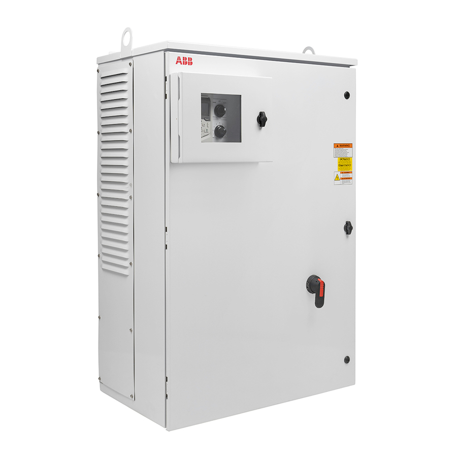
ACS580-0P 3R Irrigation Packaged Drive Installation Study these installation instructions carefully before proceeding. Failure to observe the warnings and instructions may cause a malfunction or personal hazard. WARNING! Before you begin read “Safety” on page 1. WARNING! When the ACS580 with Input Disconnect is connected to the line power, the Motor Terminals T1, T2, and T3 are live even if the motor is not running. - Page 6 ACS580-0P 3R Irrigation Packaged Drive The following figures show the front view of the ACS580 Drive with Input Disconnect standard configurations, and identify the major components. UL Type / NEMA 3R Enclosures Operating HAND Handle for Disconnect Switch Note! UL Type 3R enclosures are designed to be mounted on a wall. See section “Prepare the UL Type 3R ACS580 for UNISTRUT...
-
Page 7: Installation Flow Chart
ACS580-0P 3R Irrigation Packaged Drive Installation Flow Chart The installation of Input Disconnect configurations for ACS580 drives follows the outline below. The steps must be carried out in the order shown. At the right of each step are references to the detailed information needed for the correct installation of the unit. -
Page 8: Preparing For Installation
ACS580-0P 3R Irrigation Packaged Drive Preparing for Installation (Supplement to ACS580-01 User’s Manual) Lifting the Drive Installation... -
Page 9: Preparing For Installation
ACS580-0P 3R Irrigation Packaged Drive Preparing for Installation (Supplement to ACS580-01 User’s Manual) Drive Identification To identify the type of device you are installing, refer to the type code number on the device identification label. • Wall mounting base drives – label attached on the side surface of the heat sink. -
Page 10: Installing The Drive
ACS580-0P 3R Irrigation Packaged Drive Installing the Drive (Supplement to ACS580-01 User’s Manual) WARNING! Metal shavings or debris in the enclosure can damage electrical equipment and create a hazardous condition. Where parts, such as conduit plates require cutting or drilling, first remove the part. If that is not practical, cover nearby electrical components to protect them from all shavings or debris. - Page 11 ACS580-0P 3R Irrigation Packaged Drive Installing the Drive - continued Prepare the UL Type 3R ACS580 for UNISTRUT mounting or wall mounting ® The ACS580 UL Type 3R cabinet frame sizes are designed to be mounted on a solid vertical surface or using UNISTRUT. An optional floor/ground mounting kit is available for purchase.
- Page 12 ACS580-0P 3R Irrigation Packaged Drive Installing the Drive - continued Optional Floor/Ground Mounting Kit An optional floor/ground mounting kit is available for purchase. Installation...
-
Page 13: Mounting Optional Foot Kit On 3R Irrigation Panel
ACS580-0P 3R Irrigation Packaged Drive Assembly instructions for mounting optional foot kit on 3R irrigation panel FLOOR PLAN LAYOUT Step 1 5.01 17.74 5.01 Prepare mounting surface for enclosure. 6.81 13.62 (6) X 3/8-16 STUD GRADE 5 OR BETTER Step 2... - Page 14 ACS580-0P 3R Irrigation Packaged Drive Assembly instructions for mounting optional foot kit on 3R irrigation panel Step 3 Remove the vent plate on the right side of the enclosure to be able to assemble the hardware for the mounting feet.
- Page 15 ACS580-0P 3R Irrigation Packaged Drive Assembly instructions for mounting optional foot kit on 3R irrigation panel Step 5 Using the lifting eyes, lift the enclosure and place onto mounting studs and assemble hardware. 3/8-16 HEX NUT GRADE 5 OR BETTER...
-
Page 16: Installing The Wiring
ACS580-0P 3R Irrigation Packaged Drive Installing the Wiring (Supplement to ACS580-01 User’s Manual) Wiring Requirements Refer to the “Wiring Requirements” Section in the ACS580-01 User’s Manual. The requirements apply to all ACS580 drives. In particular: • Use separate, metal conduit runs for the following different classes of wiring: –... - Page 17 ACS580-0P 3R Irrigation Packaged Drive Typical Power Connections for Single and Three Phase CUSTOMER SUPPLIED 240/480VAC 3HP - 60Hz CUSTOMER SUPPLIED 240VAC 1HP - 60Hz DISC DISC GRN/YEL GND/PE #14 AWG BLK 230 VAC INPUT 208 VAC INPUT 460V +G304...
- Page 18 ACS580-0P 3R Irrigation Packaged Drive ACS580-0P 10-200 hp *Typical ACS580 3R irrigation panel layout Installation...
-
Page 19: Typical Control Schematic
ACS580-0P 3R Irrigation Packaged Drive Typical Control Schematic NOTES: PROGRAMMING : NO OPTIONS OR +G302 - Par 96.04 = HAND / AUTO, Par 28.11 = CONTROL REF (18). : +G302+G303 OR +G303 - Par 96.04 = HAND / AUTO DASHED LINE INDICATE CUSTOMER INSTALLED DEVICES AND WIRING. - Page 20 ACS580-0P 3R Irrigation Packaged Drive Installation...
-
Page 21: Application Guides
ACS580-0P 3R Irrigation Packaged Drive Application Guides - Hand - Auto Macro Reference voltage and analog inputs and outputs Signal cable shield (screen) Ext. speed/freq, reference (Hand): 0...10 V 1...10 kohm AGND Analog input circuit common +10V Reference voltage 10 V DC Ext. -
Page 22: Ratings
ACS580-0P Packaged Drive with Disconnect Ratings (Supplement to ACS580-01 User’s Manual) Note! The ratings listed below are exceptions to the ratings listed in the ACS580-01 User’s Manual. Technical Data... -
Page 23: Input Power Connections And Terminals
ACS580-0P Packaged Drive with Disconnect Input Power Connections and Power Connection Terminals (Supplement to ACS580-01 User’s Manual) 1-Phase 230V ABB Product Code Drive Input Fuse Incoming Power Connections Ground Output Connections to Motor Rating Lugs UL Type Amps Bussmann Minimum... -
Page 24: Dimensions And Weights
ACS580-0P Packaged Drive with Disconnect Dimensions and Weights (Supplement to ACS580-01 User’s Manual) Dimensions: ACS580-0P UL Type / NEMA 3R 32.5 Ø2.0 Ø.5 [Ø13] 26.0 HAND 49.0 52.3 3-Phase 460V 1-Phase 230V Weight Height Width Depth Weight Height Width Depth... -
Page 25: Ambient Conditions
ACS580-0P Packaged Drive with Disconnect Ambient Conditions The following table lists the ACS580 Irrigation Drive environmental requirements Ambient environment requirements Installation site Storage and transportation Altitude • 0…100m (0…330ft) • 1000m…4000m (330…13120 ft) with derating of 1% every 100m (330 ft) Ambient temperature •... -
Page 26: Applicable Standards
ACS580-0P Packaged Drive with Disconnect Applicable Standards Panel compliance with the following standards is identified by the standards “marks” on the panel. Mark Applicable Standards UL 508A UL Standard for Safety, Industrial Control Panels C22.2 No. 14 CSA Standards for Instrustrial Control Equipment Compliance is valid with the following provision: •... -
Page 27: Maintenance Intervals
If the drive is operated in a critical part of a process, fan replacement is recommended once these symptoms start appearing. Replacement fans are available from ABB. Do not use other than ABB specified spare parts. To monitor the running time of the cooling fan, see “Group 29: Maintenance Trig” in the ACS580-01 Users’s Manual. - Page 28 ABB Inc. Motion - Drives 16250 W. Glendale Drive New Berlin, WI 53151 Telephone +1 262 752-0696 Internet www.abb.com/drives...
Need help?
Do you have a question about the ACS580-0P and is the answer not in the manual?
Questions and answers