
Related Manuals for Check Point 21000 Appliances G-70


Summary of Contents for Check Point 21000 Appliances G-70
- Page 1 21000 Appliances Getting Started Guide Models: G-72, G-70 & G-50 20 February 2013 Classification: [Protected] P/N 705215...
- Page 2 Check Point. While every precaution has been taken in the preparation of this book, Check Point assumes no responsibility for errors or omissions. This publication and features described herein are subject to change without notice.
-
Page 3: Table Of Contents
21000 Appliances Hardware ................. 16 Front Panel Components ..................16 Check Point 21700 and 21600 Front Panel ............16 Check Point 21700 and 21600 Front Panel LEDS .........17 Check Point 21400 Front Panel ..............18 Check Point 21400 Front Panel LEDS ............19 Managing 21000 Appliances Using the LCD Panel ........20 Line Cards .....................21... - Page 4 Summary .......................33 Creating the Network Object ................33 Advanced Configuration ..................34 Connecting to the 21000 Appliances CLI ............34 Restoring Factory Defaults .................. 35 Restoring Using the WebUI ................35 Gaia .......................35 SecurePlatform ....................35 Restoring Using the Console Boot Menu ............35 Restoring Using the LCD Panel ................37 Registration and Support ..................
-
Page 5: Important Information
System Board Battery and for Installing and Removing a LOM card. 1 August 2011 First release of this document Feedback Check Point is engaged in a continuous effort to improve its documentation. Please help us by sending your comments (mailto:cp_techpub_feedback@checkpoint.com?subject=Feedback on 21000 Appliances Getting Started Guide). -
Page 6: Health And Safety Information
Health and Safety Information Health and Safety Information Note - The Check Point 21000 Appliances correlate with the following model numbers for certification purposes: G72, G70, and G50. Read the following warnings before setting up or using the appliance. Warning - Do not block air vents. A minimum 1/2-inch clearance is required. - Page 7 Health and Safety Information Product Disposal This symbol on the product or on its packaging indicates that this product must not be disposed of with your other household waste. Instead, it is your responsibility to dispose of your waste equipment by handing it over to a designated collection point for the recycling of waste electrical and electronic equipment.
-
Page 8: Introduction
Shipping Carton Contents Welcome Thank you for choosing Check Point’s 21000 Appliances. We hope that you will be satisfied with this system and our support services. Check Point products are the most up to date and secure solutions available today. -
Page 9: Shipping Carton Contents
Image Management guide User License Agreement * Check Point product bundles can have special appliance components. See the Check Point Website Product Catalog to learn about these special product configurations. It is necessary to log in to the Product Catalog (http://supportcenter.checkpoint.com). -
Page 10: Rack Mounting With Telescoping Rails
Front and rear rack doors must have equally distributed holes on at least 65% of the surface area to give sufficient airflow. Make sure that the racks have sufficient clearance to service the Check Point appliances that are mounted on telescoping rails. -
Page 11: Telescoping Rails Hardware
Square holes Round holes that are larger than the supplied large round-head screws Appliance Physical Specifications These are the physical specifications of the Check Point appliance models that can be mounted in the telescoping rails. Appliance Width Depth... -
Page 12: Attaching The Appliance Rails
Rack Mounting with Telescoping Rails Rack Mounting Tools Philips screwdriver. We recommend a screwdriver with a magnetic head to hold screws and retrieve dropped screws. Attaching the Appliance Rails Disconnect the appliance rail and the rack rail and use four small screws to attach each appliance rail to the sides of the appliance. -
Page 13: Installing The Appliance
Rack Mounting with Telescoping Rails Item Description Front screw plate (6 holes) Front face of the rack post Front flange Large flat-head screws To attach the rack rails to the rack: 1. Put the front flange of the rack rail on the front face of the rack post. 2. - Page 14 Rack Mounting with Telescoping Rails The telescoping rails are locked. 3. Push the front release clips and move the appliance into the rack. To secure the appliance to the rack: 1. Use two screws to attach the right ear bracket to the front face of the rack. 2.
-
Page 15: Removing The Appliance
Rack Mounting with Telescoping Rails Removing the Appliance Unlock the telescoping rails to remove the appliance from the rack. Important - A 2U appliance is heavy and two people are required to hold and remove the appliance from the rack to prevent personal injury and damage to the appliance. To remove the appliance from the rack: 1. -
Page 16: 21000 Appliances Hardware
Rear Panel Components Replacing and Upgrading Components Front Panel Components This section describes the features and components located on the appliance front panel. Check Point 21700 and 21600 Front Panel Item Description System LEDs (System power, system status, and hard disk activity). -
Page 17: Check Point 21700 And 21600 Front Panel Leds
Management port - for an Ethernet connection to a remote management computer. SYNC port - For synchronizing with cluster members or a high availability peer. USB port. Check Point 21700 and 21600 Front Panel LEDS Item Description System Power. ... -
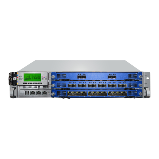
Page 18: Check Point 21400 Front Panel
ON (Green) - Link Activity OFF - No Activity Slow Blink (Amber) - Activity Check Point 21400 Front Panel Item Description System LEDs (System power, system status, and hard disk activity). LCD display screen. Keypad for LCD screen. -
Page 19: Check Point 21400 Front Panel Leds
21000 Appliances Hardware Check Point 21400 Front Panel LEDS Item Description System Power. OFF - System power off ON (Green) - System power on System Status. Green – System OK Orange – Alarm for voltage, temperature or fan. -
Page 20: Managing 21000 Appliances Using The Lcd Panel
21000 Appliances Hardware Managing 21000 Appliances Using the LCD Panel The appliance has an LCD panel that you can use to do basic management operations. You can enable DHCP. You can configure the management IP address, netmask, and default gateway of the appliance. You can reboot the appliance. -
Page 21: Line Cards
21000 Appliances Hardware Line Cards The 21000 Appliances front panel has three slots for cold-swappable Line Cards (also known as Network interface Cards (NICs)). Supported Line Cards These Line Cards are available: Item Line Card Description Supported Transceiver Transceivers Lever Color 10GbE SFP+ 10 Gb Ethernet PCI-e line Fiber-optic (short range) -
Page 22: Rear Panel Components
21000 Appliances Hardware Line Card LEDs Item Description Activity OFF - No Activity Slow Blink (Amber) - Activity Link OFF - No Link ON (Green) - Link Link OFF - No Link ON (Green) - 10Mbps or 1Gbps Link ... -
Page 23: 21700 And 21600 - Securing The Power Cable
21000 Appliances Hardware Item Description Grounding point for ESD strap. 5 replaceable CPU cooling fan units, behind the grille. Each fan unit operates independently, and provides redundancy in the event of failure. Fan grille retaining screw. The fans are redundant pairs. They are numbered from right to left: 1A/B, 2A/B, 3A/B, 4A/B, 5A/B. - Page 24 21000 Appliances Hardware To connect the power cable tie to the appliance: 1. Insert the anchor into the anchor hole on the power supply unit. Item Description Power supply unit release lever Power supply LED Anchor hole 2. Make sure that you cannot remove the cable clip from the appliance. To secure the power cable: 1.
-
Page 25: Replacing And Upgrading Components
For more information about installing these parts and components, see the appliance home page (http://supportcontent.checkpoint.com/solutions?id=sk68701). Unless directed to do so by Check Point technical support, you are prohibited by warranty and support agreements from replacing any parts. 21000 Appliances Getting Started Guide... -
Page 26: Software Configuration
Software Configuration Chapter 4 Software Configuration In This Chapter Connecting the Power Cables and Power On Available Software Images Initial Configuration Using the First Time Configuration Wizard on Gaia Using the First Time Configuration Wizard on SecurePlatform Creating the Network Object Advanced Configuration Connecting the Power Cables and Power On To connect the power cables:... -
Page 27: Using The First Time Configuration Wizard On Gaia
Software Configuration Go to the applicable section: Using the First Time Configuration Wizard on Gaia (on page 27) Using the First Time Configuration Wizard on SecurePlatform (on page 31) Using the First Time Configuration Wizard on Gaia Use the First Time Configuration Wizard to do the initial configuration of the Gaia appliance. Note - The pages that you see in the wizard depend on the software image and the options you select. -
Page 28: Date And Time Setup
Software Configuration Date and Time Setup Set the system time and date for the appliance: Manually From a time server, using Network Time Protocol (NTP) Device Name Set the host name, domain name, and DNS servers for IPv4 addresses. The host name must start with a letter and cannot be named com1, com2..com9. -
Page 29: Products
Software Configuration Products Products Select the Gaia products that are installed on the appliance. Advanced Use these options to configure an appliance that is a cluster member or in a High Availability deployment. Unit is part of a cluster - the options are: ... -
Page 30: Security Management Administrator
Software Configuration Security Management Administrator Note - You only see this page when the Gaia appliance is a Security Management server. Define the name and password of an administrator that can connect to the Security Management server using SmartConsole clients. Security Management GUI Clients Note - You see this page when the appliance is a Security Management. -
Page 31: Using The First Time Configuration Wizard On Secureplatform
Software Configuration Using the First Time Configuration Wizard on SecurePlatform Do the initial configuration of the SecurePlatform appliance with the First Time Configuration Wizard. Note - The pages that you see in the wizard depend on the software image and the options you select. You will not see all the pages that are in this section. -
Page 32: Network Connections
Configure the cluster type. If you select This appliance is part of a 21000 Appliances Cluster, the options are: Primary cluster member Secondary cluster member For information about clusters, see the ClusterXL Administration Guide (http://supportcenter.checkpoint.com) for your Check Point version. 21000 Appliances Getting Started Guide | 32... -
Page 33: Summary
Type page) requires you to install the SmartConsole applications. In the Download SmartConsole Applications window, you can download SmartConsole and install it on Windows machines. The release notes of your Check Point version in the Check Point Support Center (http://supportcenter.checkpoint.com), lists compatible Windows operating systems for SmartConsole. -
Page 34: Advanced Configuration
Software Configuration 2. Configure a new gateway object for the appliance. 3. Enter the IP address for the appliance. 4. For a centrally managed deployment, establish Secure Internal Communication (SIC). Enter the activation key you used in the First Time Configuration Wizard. 5. -
Page 35: Restoring Factory Defaults
Chapter 5 Restoring Factory Defaults In This Chapter Restoring Using the WebUI Restoring Using the Console Boot Menu Restoring Using the LCD Panel If necessary, restore the appliance to its factory default settings. Important - If you restore factory defaults, all information on the appliance is deleted. - Page 36 Restoring Factory Defaults 2. Connect to the appliance using a terminal emulation program such as Microsoft HyperTerminal or PuTTY. 3. Configure the terminal emulation program: In the HyperTerminal Connect To window, select a port from the Connect using list. ...
-
Page 37: Restoring Using The Lcd Panel
Restoring Factory Defaults Restoring Using the LCD Panel To restore the appliance to its default factory configuration using the LCD Panel keys: 1. Reboot or turn on the appliance. 2. When the countdown begins, press an arrow key. The Boot menu shows. 3. -
Page 38: Registration And Support
For additional technical information about Check Point products, consult the Check Point Support Center (http://supportcenter.checkpoint.com). Where To From Here? You have the basics to get started. The next step is to get more advanced knowledge of your Check Point software. Check Point documentation is available on the Check Point Support Center (http://supportcenter.checkpoint.com). -
Page 39: Compliance Information
This appendix contains declaration of conformity, compliance, and related regulatory information. In This Appendix Declaration of Conformity Declaration of Conformity Manufacturer’s Name: Check Point Software Technologies Ltd. Manufacturer’s Address: 5 Ha'Solelim Street, Tel Aviv 67897, Israel Declare that under our sole responsibility the products... - Page 40 Compliance Information EN 55024 Information Technology Equipment - Immunity Characteristics EN61000-4-2 Information Technology Equipment - Electrostatic Discharge Immunity EN61000-4-3 Information Technology Equipment - Radiated RF Immunity EN61000-4-4 Information Technology Equipment - Fast Transient Immunity EN61000-4-5 Information Technology Equipment - Surge Immunity EN61000-4-6 Information Technology Equipment - Conducted RF Immunity...
Need help?
Do you have a question about the 21000 Appliances G-70 and is the answer not in the manual?
Questions and answers