Advertisement
PROFESSIONAL TORQUE TESTER
PRO-TEST 40, 400 & 1500ER
OPERATOR'S HANDBOOK (PART No 34237) Issue 4
FOR USE WITH PRO-TEST'S FITTED WITH VERSION 37701.101 & 37701.102 SOFTWARE
NORBAR TORQUE TOOLS LTD, Beaumont Road, Banbury, Oxon, OX16 7XJ, UNITED KINGDOM
Tel : + 44 (0) 1295 270333,
(ENGLISH)
MODEL NUMBERS COVERED BY THIS MANUAL
43180
PRO-TEST 40 TRANSDUCER
43181
PRO-TEST 400 TRANSDUCER
43189
PRO-TEST 1500ER TRANSDUCER
43184
PRO-TEST DISPLAY MODULE
Fax : + 44 (0) 1295 753643
Advertisement

Related Manuals for norbar PRO-TEST 40


Summary of Contents for norbar PRO-TEST 40
- Page 1 PRO-TEST 40 TRANSDUCER 43181 PRO-TEST 400 TRANSDUCER 43189 PRO-TEST 1500ER TRANSDUCER 43184 PRO-TEST DISPLAY MODULE NORBAR TORQUE TOOLS LTD, Beaumont Road, Banbury, Oxon, OX16 7XJ, UNITED KINGDOM Tel : + 44 (0) 1295 270333, Fax : + 44 (0) 1295 753643...
-
Page 2: Table Of Contents
CONTENTS PAGE Introduction Assembly Diagram Operating Instructions Set Up Menus and Options RS-232-C Serial Data Output Interface Print Inhibit Controller Option Specifications Trouble Shooting... -
Page 3: Introduction
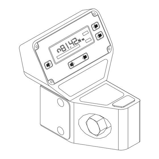
Optional extra’s include a Mounting Bracket, 1” sq x 36mm Hex Socket, Print Inhibit Controller, Data Printer and 12 Volt DC power supply for use in vehicles. ASSEMBLY DIAGRAM 43184 38793 25429 43180 PRO-TEST 40 43180 PRO-TEST 40 43181 PRO-TEST 400 43181 PRO-TEST 400... -
Page 4: Operating Instructions
PRO-TEST OPERATORS HANDBOOK PAGE 2 OF 10 ISSUE 4 AUGUST 1998 OPERATING INSTRUCTIONS Securely mount the Pro-Test transducer in the plane of operation required to a bench top,wall or the additional mounting bracket (part number 62198) with the 2 fixing bolts supplied. IMPORTANT ! The un-bolted end of the unit, must always be in contact with a supporting surface. - Page 5 PRO-TEST OPERATORS HANDBOOK PAGE 3 OF 10 ISSUE 4 AUGUST 1998 Plug Power Supply into back of transducer housing then plug mains lead into Power Supply. If a mains plug is not fitted, wire as follows : BROWN-LIVE BLUE-NEUTRAL GREEN / YELLOW-EARTH WARNING! It is important that live, neutral and earth are all connected between the Pro-Test and mains power supply.
-
Page 6: Set Up Menus And Options
PRO-TEST OPERATORS HANDBOOK PAGE 4 OF 10 ISSUE 4 AUGUST 1998 SET UP MENUS AND OPTIONS SELECT UNITS MODE> TRACK PRINT ZERO To enter ‘SET UP’ mode, press ‘SELECT UNITS’ & ‘PRINT’ buttons simultaneously, then release upon which the ‘SOFTWARE VERSION NUMBER’ will be displayed for 2 seconds. LANGUAGE MENU EXIT ENGLISH... - Page 7 PRO-TEST OPERATORS HANDBOOK PAGE 5 OF 10 ISSUE 4 AUGUST 1998 RS 232 C PARAMETERS MENU EXIT PARITY OFF DATA BITS 8 STOP BITS 2 LEADING CHARACTER BLANK OUTPUT UNITS YES ê EVEN/ODD/OFF ZERO Select desired parameter by repeatedly pressing ‘ê‘ until text flashes. To change the setting, press the bottom right hand button, this button changes its function as each parameter is selected.
-
Page 8: Rs-232-C Serial Data Output Interface
PRO-TEST OPERATORS HANDBOOK PAGE 6 OF 10 ISSUE 4 AUGUST 1998 RS-232-C SERIAL DATA OUTPUT INTERFACE Output of both measured value and units of measurement (as shown on the display) are in a familiar serial data format for communication with computers, printers, etc. Data is output on the RS-232-C interface automatically when the memory auto-reset mode timer operates, when the 'MEMORY RESET' button is pressed, or by pressing the PRINT’... -
Page 9: Print Inhibit Controller Option
PRO-TEST OPERATORS HANDBOOK PAGE 7 OF 10 ISSUE 4 AUGUST 1998 MITUTOYO DATA PROCESSORS :-___________________________________________________ The instrument can be configured to communicate to Mitutoyo DP3DX, DP7, QM1000 and QM5000 families of data processors. For DP3DX, DP7, QM1000 and QM5000 families, the units of measurement must be inhibited. For DP3DX and DP7 families, a '+' character must be added to the start of the data stream This is in addition to the units of measurement being inhibited. -
Page 10: Specifications
PRO-TEST OPERATORS HANDBOOK PAGE 8 OF 10 ISSUE 4 AUGUST 1998 SPECIFICATIONS PRO - TEST TRANSDUCER SPECIFICATION :- _________________________________________ PRO-TEST 40 PRO-TEST 400 PRO-TEST 1500ER RANGE OF 0 to 40 N.m 0 to 400 N.m 0 to 1500 N.m OPERATION CALIBRATION 5% to 100% of full scale. - Page 11 TRACK None. ALL MEMORY MODES Suppressed from 0 to approximately 0.5% of transducer calibration range. UNITS OF MEASUREMENT PRO-TEST 40 N.m, dN.m, cN.m, lbf.ft, lbf.in, ozf.in, kgf.m, kgf.cm. (Menu Selectable). PRO-TEST 400 N.m, dN.m, lbf.ft, lbf.in, kgf.m, kgf.cm. (Menu Selectable).
-
Page 12: Trouble Shooting
To maintain the specified accuracy it is recommended that the Pro-Test transducers are recalibrated at least once per year. Recalibration and repair should be carried out at Norbar or by a Norbar approved agent, where all the facilities to ensure the instrument is functioning at maximum accuracy are available.
Need help?
Do you have a question about the PRO-TEST 40 and is the answer not in the manual?
Questions and answers