Thermo Scientific TSX Series Installation And Operation Manual
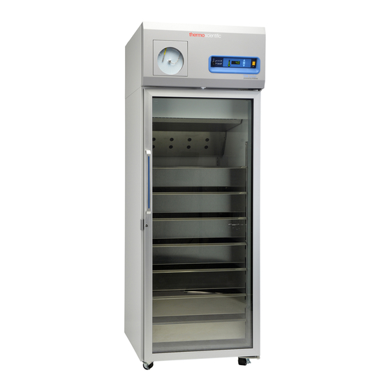
Blood bank refrigerators
Hide thumbs
Also See for TSX Series:
- Installation and operation manual (81 pages) ,
- Installation and operation manual (40 pages) ,
- Installation and operation manual (43 pages)

Related Manuals for Thermo Scientific TSX Series


Summary of Contents for Thermo Scientific TSX Series
- Page 1 Blood Bank Refrigerators TSX Series Installation and Operation 327930H01 Rev. A August 2016 Visit us online to register your warranty www.thermofisher.com/labwarranty...
- Page 2 IMPORTANT Read this instruction manual. Failure to follow the instructions in this manual can result in damage to the unit, injury to operating personnel, and poor equipment performance. CAUTION All internal adjustments and maintenance must be performed by qualified service personnel. Material in this manual is for informational purposes only.
-
Page 3: Table Of Contents
Table of Contents Table of Contents Models ..................1 Safety Precautions..............2 Unpacking.................4 Packing List ................5 General Recommendations .............6 Temperature Monitoring ............6 Intended Use ................6 Operating Standards ...............7 Unit Specifications ...............7 Installation................8 Location ................8 Leveling ................8 Wiring ..................8 Shelves .................9 Drawers ................9 Baskets ................13 Anti-Tip Brackets ...............13 Temperature Sensor Bottles ..........16... - Page 4 Table of Contents Cleaning the Cabinet Interior ..........30 Cleaning the Condenser Filter ..........30 Cleaning the Condenser .............30 Automatic Defrost ..............31 Gasket Maintenance ............31 Alarm Battery Maintenance ..........31 Troubleshooting ..............32 End of Life Care..............34 Warranty ................35...
-
Page 5: Models
Models 1 Models The table below shows the units covered in this operation and installation manual by model number. Refer Section 6.1 for details on the voltage specifications for the various models. Table 1. Applicable Models Unit Model (*) Thermo Scientific - TSX2304B* A/D/V Thermo Scientific TSX Blood Bank Refrigerators... -
Page 6: Safety Precautions
Safety Precautions 2 Safety Precautions In this manual, the following symbols and conventions are used: This symbol when used alone indicates important operating instructions which reduce the risk of injury or poor performance of the unit. WARNING: This symbol indicates potentially hazardous situations which, if not avoided, could result in serious injury or death. - Page 7 Safety Precautions Below are important safety precautions that apply to this product: Use this product only in the way described in the product literature and in this manual. Before using it, verify that this product is suitable for its intended use. If the equipment is used in a manner not specified by the manufacturer, the protection provided by the equipment may be impaired.
-
Page 8: Unpacking
Unpacking 3 Unpacking At the time of delivery, be sure to inspect the unit packaging for damage before signing for the shipment. If packaging damage is present, request immediate product inspection and file a claim with the carrier. Note Packaging damage does not denote that unit damage exists. If concealed damage is found (damage that is not apparent until the item has been unpacked), stop further unpacking and save all packing for carrier's inspection. -
Page 9: Packing List
Packing List 4 Packing List Inside the refrigerator cabinet is a bag containing: • USB drive with this and other user manuals, including translated versions • Certificate of Conformance • Warranty Card • Safety Data Sheet for Glycerin • Quick start guide •... -
Page 10: General Recommendations
General Recommendations 5 General This section includes some general recommendations for your unit. Recommendations 5.1 Temperature Monitoring IMPORTANT NOTE We recommend the use of a redundant and independent temperature monitoring system so that the refrigerator can be monitored continuously for performance commensurate with the value of product stored. -
Page 11: Operating Standards
Operating Standards 6 Operating The refrigerators described in this manual are classified for use as stationary Standards equipment in a Pollution Degree 2 and Overvoltage Category II environment. These units are designed to operate under the following environmental conditions: • Indoor use •... -
Page 12: Installation
Installation 7 Installation WARNING: Do not exceed the electrical rating printed on the dataplate located on the upper left side of the unit. 7.1 Location Install the unit on a level area free from vibration with a minimum of 6 inches of space on the sides and rear and 12 inches at the top. -
Page 13: Shelves
Installation CAUTION: Never cut the grounding prong from the service cord plug. If the prong is removed, the warranty is invalidated. CAUTION: In an emergency, the power cord is a disconnected device. 7.4 Shelves Blood Bank Refrigerators have the option to be ordered with 4 wire shelves. Additional shelves are offered as available options. - Page 14 Installation Figure 2. Drawer Removal Label Description Tabs Drawer slide Slot To reinstall the drawers, complete the following steps (refer to Figure 2): 7.5.2 Reinstalling the Drawers 1. Pull both the slides of the drawer towards you until the slides are fully extended.
- Page 15 Installation Figure 3. Clip Removal 3. Lift up the slide at the front. The slide is free to move from the front pilaster. Figure 4. Front of slide Removal 4. The drawer slide must be removed from the rear pilaster at approximately a 45 degree angle towards the center of the cabinet.
- Page 16 Installation 5. Pull the slide towards the front of the cabinet. 6. Determine desired location for the slide and insert the slide into the rear pilaster at a 45 degree angle towards the center of the cabinet. 7. Once the slide is seated in the rear pilaster, rotate the slide until it is parallel with the unit wall and insert slide into front pilaster.
-
Page 17: Baskets
Installation 7.6 Baskets Blood Bank Refrigerators have the option to order 6 wire baskets. Baskets are shipped in a factory installed position that promotes uniform spacing between the baskets. The basket slides are adjustable to higher and lower positions in the cabinet. You can position these slides in the vertical slots which are spaced at one-inch intervals. - Page 18 Installation Table 4. Tools required Wood Floor Concrete Floor Flashlight Tape Measure " (13 mm) Wrench " (19 mm) Wrench Drill Hammer Drill " " 15/64 (6 mm) Drill Bit (13 mm) Masonry Bit 1. Locating the Bracket a. Determine where you want the centerline of the refrigerator to be. b.
- Page 19 Installation Figure 9. Bolt Location Label Description Back of Unit 1/2" Bolt Location Detailed View Lock Nut 1/2" Bolt Floor 1/2" Clearance 4. Refrigerator Positioning a. Line up 1/2" bolt installed in step 3 with anti-tip bracket. b. Roll or slide refrigerator into position until bolt stops against bracket.
-
Page 20: Temperature Sensor Bottles
Installation 7.8 Temperature Sensor The temperature displayed on the control panel and chart recorder are measured by probes inserted in the sensor bottles inside the cabinet. The sensor probes Bottles must be inserted in the glycol bottle prior to operation. There are two sensor bottles at different heights. -
Page 21: Final Checks
Installation Remote alarm terminals are located at the rear of the machine compartment. The three terminals are: COMMON, OPEN ON FAIL (Normally Closed), and CLOSE ON FAIL (Normally Open). Figure 10. Remote Alarm Diagram To install the remote alarm, make the following connections: 1. -
Page 22: Startup
Startup 8 Startup 8.1 Initial Startup To start up the refrigerator, complete the following steps: 1. Verify that the sensor probe(s) have been installed in the bottle(s) as described in Section 7.8. 2. Ensure the double pole circuit breaker switch located next to the power inlet is in “ON”... -
Page 23: Operation
Operation 9 Operation 9.1 Control Panel Figure 11. Refrigerator Control Panel The control panel is located on the top right side of your blood bank refrigerator. You can use the three pushbuttons (#5, #8, and #9 in Figure 11) to change the temperature display (#1) or to adjust temperature and alarm setpoints as given in Section 9.3. - Page 24 Operation Table 6. Thermometer Display on Control Panel (Setpoint 4°C) Bars Temperature Bars Temperature Displayed (°C) Displayed (°C) Bulb Only 2 (cold alarm) 6 Bars 1 Bar 2.35 7 Bars 4.45 2 Bars 8 Bars 3 Bars 3.05 9 Bars 5.15 4 Bars 10 Bars...
-
Page 25: Display Functions
Operation 12. Key Switch - switch used to turn the power and alarms on and off for the unit. 13. Alarm On - Setpoint Security - when the key switch is in the alarm on position, the alarms are on and the setpoints cannot be modified. 14. -
Page 26: Programming Functions
Operation 9.3 Programming You can enter the programming mode by pressing the Scan button ( ) and holding for 5 seconds. The display will then flash "Prg" to indicate that you Functions have entered the programming mode. Use ( ) and ( ) buttons to modify the values and press the scan ( ) button to save the value and go to the next screen. - Page 27 Operation Table 9. Service Parameters Screen/Button Display Function Summary Allows the user to see what temperature the unit is designed to Temp of unit Varies CPU Checksum Shows the current checksum of the CPU board for validation Initial Screen Relay Board Varies Shows the current checksum of the Relay board for validation Checksum...
-
Page 28: Temperature Settings
Operation If the unit is left idle for a period of 30 seconds during service mode, the unit will exit service mode and return to normal operation. Note If an alarm occurs while in the service mode, it will not show until exiting this mode. - Page 29 Operation power failure, temperature alarm condition, or when the door is ajar for more than 3 minutes. The Mute function (pressing the button) allows you to turn off the audio warning without turning off the visual indicators. The alarm will ring back approximately after 6 minutes if the alarm is still active.
-
Page 30: Chart Recorder
Chart Recorder 10 Chart Recorder Panel-mounted six inch recorders are standard and factory-installed on all models. Recorder operation begins when the system is powered on. 10.1 Set Up and To prepare the recorder to function properly, complete the following steps: Operation 1. -
Page 31: Changing Chart Paper
Chart Recorder Figure 13. Chart Buttons 10.2 Changing Chart To change the chart paper, complete the following steps: Paper 1. Locate the pressure sensitive buttons at the front, upper left of the recorder panel. 2. Press and hold the change chart button (#3 in Figure 13) for one second. The pen will move off the scale. -
Page 32: Calibration And Adjustments
Chart Recorder 10.4 Calibration and This recorder has been accurately calibrated at the factory and retains calibration even during power interruptions. If required, however, adjustments can be made Adjustments as follows: 1. Run the unit continuously at the control setpoint temperature. Continue steady operation for at least two hours to provide adequate time for recorder response. -
Page 33: Temperature Transmitter (Optional)
Temperature Transmitter (Optional) 11 Temperature A powered temperature transmitter is an option for all units. This temperature Transmitter transmitter allows for remote temperature monitoring of your system. (Optional) To connect your remote temperature monitoring system to the temperature transmitter, refer to Figure 14 below. Figure 14. -
Page 34: Maintenance
Maintenance 12 Maintenance WARNING: Disconnect equipment from main power before attempting any maintenance to equipment or its controls unless stated otherwise. 12.1 Cleaning the To clean the cabinet interior, remove the shelves, drawers and baskets following the instructions in Section 7.4, Section 7.5 and Section 7.6. Use a solution of Cabinet Interior water and a mild detergent for cleaning. -
Page 35: Automatic Defrost
Maintenance 3. Vacuum the condenser and clean up any loose dust. 4. Replace the filter. 5. Reconnect power. 12.4 Automatic Defrost The defrosting process on all models is primarily accomplished by air circulated during off-cycle periods. This heat-free process ensures that the temperature is not affected by the defrost cycle. -
Page 36: Troubleshooting
Troubleshooting 13 Troubleshooting WARNING: Troubleshooting procedures involve working with high voltages which can cause injury or death. Troubleshooting should only be performed by trained personnel. This section is a guide for troubleshooting equipment problems. Table 10. Troubleshooting Procedures Problem Cause Solution Check that the cord is securely plugged in. - Page 37 Troubleshooting Table 10. Troubleshooting Procedures Problem Cause Solution Door is open Make sure the door is completely closed. Section 12.5 Door seal Check the door seal, following instructions in Warm product Allow ample time to recover from loading warm product. recently loaded in unit Unit warms up...
-
Page 38: End Of Life Care
End of Life Care 14 End of Life Care Be sure to follow local regulations when disposing of an old unit. Some suggestions are listed in the following: 1. Remove items and defrost unit. Be sure to clean up any biological safety hazards. -
Page 39: Warranty
Warranty 15 Warranty Domestic Warranty • 24 Months Full Warranty Parts and Labor International Warranty • 24 Months Full Warranty Parts Only During the first twenty four (24) months from shipment, Thermo Fisher Scientific Inc, through its authorized Dealer or service organizations, will at its option and expense repair or replace any part found to be non-conforming in material or workmanship. - Page 40 WEEE Compliance WEEE Compliance. This product is required to comply with the European Union’s Waste Great Britain Electrical & Electronic Equipment (WEEE) Directive 2012/19/EU. It is marked with the following symbol. Thermo Fisher Scientific has contracted with one or more recycling/disposal companies in each EU Member State, and this product should be disposed of or recycled through them.
- Page 41 IF YOU NEED ASSISTANCE: Thermo Fisher Scientific products are backed by a global technical support team ready to support your applications. We offer cold storage accessories, including remote alarms, temperature recorders, and validation services. Visit www.thermofisher.com or call: Phone Numbers Sales Service North America...
- Page 42 Thermo Fisher Scientific Inc. 275 Aiken Road Asheville, NC 28804 United States www.thermofisher.com 327930H01 Rev. A...
Need help?
Do you have a question about the TSX Series and is the answer not in the manual?
Questions and answers