Sign In
Upload
Manuals
Brands
Parker Manuals
Servo Drives
PSD1-M_1400
Parker PSD1-M_1400 Manuals
Manuals and User Guides for Parker PSD1-M_1400. We have
2
Parker PSD1-M_1400 manuals available for free PDF download: Installation Instructions Manual, Quick Manual
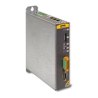
Parker PSD1-M_1400 Installation Instructions Manual (109 pages)
Brand:
Parker
| Category:
Servo Drives
| Size: 8 MB
Table of Contents
Table of Contents
3
1 What Is Necessary and Where to Find It
6
2 Introduction
7
Device Assignment
7
Scope of Delivery
7
Type Identification Plate PSD1-S and PSD1-M with Safety Option Board
7
Type Identification Plate PSD1-M
8
Order/ Type Code PSD
9
Designated Use
9
Packaging, Transport, Storage
10
For Safety Use
11
Explanation of the Safety Instructions
11
Working Safely / Qualification
11
General Hazards
11
Special Dangers
11
Cautionary Markings
12
Responsibility
13
Warranty Conditions
13
Conditions of Utilization
13
Conditions of Utilization for CE-Conform Operation
13
CE Declaration of Conformity PSD1-M
16
CE Declaration of Conformity PSD1-S
17
Conditions of Utilization for the Cul Certification of PSD1-M
18
Conditions of Utilization for the Cul Certification of PSD1-S
21
Current on the Mains PE (Leakage Current)
24
Supply Networks
24
Before Commissioning the Drive, Please Observe the Following
25
3 PSD: PSD -Parker Servo Drive - Overview
26
4 Installation of the Individual Drive PSD1-S
27
Before Commissioning the Drive, Please Observe the Following
27
Mounting and Dimensions
27
Mounting and Dimensions
28
Mounting and Dimensions PSD1-S
28
Connector Overview PSD1-S
28
Connector Overview PSD1-S
29
Front View (PSD1-S)
29
In this Chapter You Can Read about
29
View from below (PSD1-S)
30
View from above (PSD1-S)
31
P14: Status LED (PSD1-S)
31
X17: Digital Inputs / Outputs (PSD1-S)
32
Control Voltage 24 VDC PSD1-S
33
Wiring of the Digital Inputs and Outputs
33
X63: AC Mains Supply, DC Voltage Supply & Connection of Braking Resistor (PSD1-S)
33
Mains Connection PSD1-S
34
Braking Operation PSD1-S
34
X52: Motor Connection (PSD1-S)
35
Motor Connection with Self-Made Motor Cable
35
Output Data PSD1-S 1/3*230 VAC
36
Motor Feedback
36
X51: Motor Holding Brake and HIPERFACE DSL® Connection
36
X18: Connector Assignment with Configured Resolver Feedback
37
X18: Assignment with Configured Incremental Encoder or Analogue Hall
38
X60: PC-/Diagnostic Interface
38
Communication Interfaces
39
X61, X62 Ethernet Connection
39
5 Installation of the Multi-Axis System PSD1-M
40
Before Commissioning the Drive, Please Observe the Following
41
Mounting and Dimensions
41
Accident Prevention Measures Must be Observed
41
Before Wiring or Loosening Electrical Connections Please Observe the
41
Caution! Dangerous Electrical Voltage Even after Turning off the Intermediate
41
CAUTION: Risk of Electric Shock
41
Disconnect the Devices from the Mains Supply
41
Mains Supply, Dangerous Voltages May Still be Present
41
Only Qualified Electrician May Commission the Drive
41
Risk of Electric Shock, Disconnect Power before Removing Cover Resp
41
Mounting and Dimensions PSD1-M Size 1
42
Mounting and Dimensions PSD1-M Size 2
43
Connector Overview PSD1-M
44
Front View (PSD1-M)
44
In this Chapter You Can Read about
44
View from below (PSD1-M)
46
View from above (PSD1-M)
47
P14
47
X17: Digital Inputs / Outputs Axis 1 & 3 (PSD1-M)
49
X21: Digital Inputs / Outputs Axis 2 & 3 (PSD1-M)
49
Wiring of the Digital Inputs and Outputs
50
Motor Connection / Output Data
51
Output Data Servo Modules PSD1-M 3*400 VAC
51
Output Data of the PSD1-M Power Output Stages
51
X45: Motor Connection (PSD1-M)
52
X43: Motor Connection (PSD1M_1800)
53
Motor Feedback
54
X48: HIPERFACE DSL® & Motor Temperature Sensor (PSD1-M)
54
X18, X19, X20 Connector Assignment with Configured Resolver
55
X18, X19, X20: Assignment with Configured Incremental Encoder or Analogue Hall
55
X46: Connection of Motor Brake (PSD1-M)
56
X44: Connection of Motor Brake (PSD1M_1800)
57
Mains Module PSD1-M_P
57
Connector Overview PSD1-M_P (Mains Module)
57
P1: Status - Leds - Indication (Mains Module)
59
S2: Modes Switch (Power Module)
60
S3: Voltage Switch (Power Module)
60
Connections of the Axis System
61
X9: Control Voltage 24 VDC Mains Module
62
X41 Mains Supply (Mains Module PSD1-M_P)
62
X40: Braking Resistor / Temperature Switch PSD1-M_P (Power Supply)
64
X4: Inputs / Outputs of the Mains Module
65
X60: PC-/Diagnostic Interface
66
Communication Interfaces
66
X61, X62 Ethernet Connection
66
6 Safe Torque off (STO) with PSD1
67
General Description
67
Important Technical Terms and Explanations
67
Applications in Accordance with the Regulations
68
Qualified Personnel
68
Advantages of Using the "Safe Torque Off" Safety Function" STO
68
Advantages of Using the "Safe Torque Off" Safety Function" STO
69
STO Operating Principle
69
In this Chapter You Can Read about
69
STO Principle of PSD1-S with One Axis Module
70
STO Principle with PSD1-S
70
STO Principle of PSD1-M with Two Axis Modules
71
STO Principle of PSD1-M with Three Axis Modules
72
Notes on the STO Function
73
Conditions of Utilization for the STO Function
73
STO Delay Times
74
STO Application Examples
75
STO and SS1 Function with External Safety Control
75
In this Chapter You Can Read about
75
STO Function Without External Safety Control
76
STO Function Test
78
STO Test Protocol Specimen
79
Technical Data STO
80
7 Accessories
81
SMH Servo Motors with HIPERFACE DSL® - Feedback
81
Order Code of Motor Cable
82
EMC Measures
82
Mains Filter
82
Motor Output Chokes
84
Line Choke
87
Line Choke für PSD1-M_P010: 0.86 Mh / 30 a
87
Line Choke for PSD1_M_P020: 0.45 Mh / 55 a
87
External Braking Resistors
88
Overview Braking Resistors PSD1
89
Braking Resistor ACB-0004-01
89
Braking Resistor ACB-0005-01 & ACB-0005-02
90
Braking Resistor ACB-0001-1 and ACB-0002-1
91
Braking Resistor ACB-0003-01 for PSD1-M_P020
92
Interface Cables
93
Ethernet Cables: CBD000C0-T00-T00-XXXX-00
93
8 Technical Data
94
PSD1-S: Single Device
94
Mains Connection PSD1-S
94
Output Data PSD1-S 1/3*230 VAC
95
Control Voltage 24 VDC PSD1-S
95
Braking Operation PSD1-S
95
Size / Weight of PSD1-S
95
PSD1-M: Multi-Axes System
96
Mains Connection Power Module PSD1-M_P010 Without Line Choke
96
Mains Connection Power Module PSD1-M_P010 with Line Choke
96
In this Chapter You Can Read about
96
Mains Connection Power Module PSD1-M_P020 Without Line Choke
97
Mains Connection Power Module PSD1-M_P020 with Line Choke
97
Output Data Servo Modules PSD1-M 3*400 VAC
98
Output Data of the PSD1-M Power Output Stages
98
Control Voltage 24 VDC PSD1-M_P (Mains Module)
99
Braking Operation PSD1-M
99
Dynamic Braking Module
99
Size / Weight PSD1-M
100
Motors/ Feedback/ Motor Holding Brake
100
Motor Technologies Supported
100
Feedback System HIPERFACE DSL
101
Resolver
101
Incremental Encoder / Analogue HAL Sensor
101
Motor Holding Brake Output
102
Digital Inputs / Outputs (Specifications)
102
Technical Data STO
103
EC Directives and Applied Harmonized EC Norms (PSD1)
103
EMC Limit Values PSD1
103
Insulation Requirements PSD1
104
Environmental Requirements PSD1
104
Cul Certification
104
Ethercat Characteristics
104
PROFINET Characteristics
105
Ethernet IP Characteristics
105
9 Index
106
Advertisement
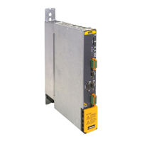
Parker PSD1-M_1400 Quick Manual (31 pages)
Brand:
Parker
| Category:
Servo Drives
| Size: 2 MB
Table of Contents
Table of Contents
3
What Is Necessary and Where to Find It
4
Introduction
5
Device Assignment
5
Scope of Delivery
5
Type Identification Plate PSD1-M
5
In this Chapter You Can Read about
5
Type Identification Plate PSD1-S and PSD1-M with Safety Option Board
6
Designated Use
6
Packaging, Transport, Storage
6
For Safety Use
7
Explanation of the Safety Instructions
7
Working Safely / Qualification
8
General Hazards
8
Special Dangers
8
Cautionary Markings
9
Before Commissioning the Drive, Please Observe the Following
10
Warranty Conditions
10
Responsibility
10
Conditions of Utilization
11
Conditions of Utilization for CE-Conform Operation
11
CE Declaration of Conformity PSD1-M
13
Conditions of Utilization for the Cul Certification of PSD1-S
13
Plug and Device Overview PSD1-M
14
Front View (PSD1-M)
15
View from below (PSD1-M)
16
View from above (PSD1-M)
18
Signal Interfaces IO Optionboard
19
Plug and Device Overview PSD1-M_P (Mains Module)
21
Front View (PSD1-M_P Mains Module)
21
View from below (PSD1-M_P Mains Module)
22
Mounting and Dimensions
23
Mounting and Dimensions PSD1-M Size 1
24
Mounting and Dimensions PSD1-M Size 2
25
Technical Data
26
Mains Connection Power Module PSD1-M_P010 Without Line Choke
26
Mains Connection Power Module PSD1-M_P010 with Line Choke
27
Mains Connection Power Module PSD1-M_P020 Without Line Choke
27
Mains Connection Power Module PSD1-M_P020 with Line Choke
28
Environmental Requirements PSD1
28
Size / Weight PSD1-M
29
Index
30
Advertisement
Related Products
Parker PSD1-M_1300
Parker PSD1-M_1600
Parker PSD1-M_1800
Parker PSD1-M_2220
Parker PSD1-M_2440
Parker PSD1-M_2630
Parker PSD1-M_3222
Parker PSD1-M_3433
Parker PSD1-MWP010
Parker PSD1-MWP020
Parker Categories
Controller
Control Unit
Industrial Equipment
Water Filtration Systems
DC Drives
More Parker Manuals
Login
Sign In
OR
Sign in with Facebook
Sign in with Google
Upload manual
Upload from disk
Upload from URL