Sign In
Upload
Download
Table of Contents
Contents
Add to my manuals
Delete from my manuals
Share
URL of this page:
HTML Link:
Bookmark this page
Add
Manual will be automatically added to "My Manuals"
Print this page
×
Bookmark added
×
Added to my manuals
Manuals
Brands
Parker Manuals
Servo Drives
PM-FBL Series
User manual
Parker PM-FBL Series User Manual
New servo system
Hide thumbs
1
2
Table Of Contents
3
4
5
6
7
8
9
10
11
12
13
14
15
16
17
18
19
20
21
22
23
24
25
26
27
28
29
30
31
32
33
34
35
36
37
38
39
40
41
42
43
44
45
46
47
48
49
50
51
52
53
54
55
56
57
58
59
60
61
62
63
64
65
66
67
68
69
70
71
72
73
74
75
76
77
78
79
80
81
82
83
84
85
86
87
88
89
90
91
92
93
94
95
96
97
98
99
100
101
102
103
104
105
106
107
108
109
110
111
112
113
114
115
116
117
118
119
120
121
122
123
124
125
126
127
128
129
130
131
132
133
134
135
136
137
138
139
140
141
142
143
144
145
146
147
148
149
150
151
152
153
154
155
156
157
158
159
160
161
162
163
164
165
166
167
168
169
170
171
172
173
174
175
176
177
178
179
180
181
182
183
184
185
186
187
188
189
190
191
192
193
194
195
196
197
198
199
200
201
202
203
204
205
206
207
208
209
210
211
212
213
214
215
216
217
218
219
220
221
222
223
224
225
226
227
228
229
230
231
232
233
234
235
236
237
238
239
240
241
242
243
244
245
246
247
248
249
250
251
252
253
254
255
256
257
258
259
260
261
262
263
264
265
266
267
268
269
270
271
272
273
274
275
276
277
278
279
280
281
282
283
284
285
286
page
of
286
Go
/
286
Contents
Table of Contents
Bookmarks
Table of Contents
Table of Contents
Table of Figures
Important User Information
Change Summary
Introduction
P Series Products Overview
P Series Features
PD Drive Names
Input Power
Figure 1. PD Drive Names
Front Panel Description of Representative Drives
Figure 2. 400W Drive Front Description
Table 1. Output Power Level
PM Motor Names
Figure 3. 1000W Drive Front Description
Figure 4. 3500W Drive Front Description
Options
Compatible Parker Product
Figure 5. PM Motor Names
Assumptions of Technical Experience
Technical Support
Mechanical Installation
Environment
Table 2. Drive Installation Environment
Dimensions
PD Drive Dimensions (PD-01Xx to PD-35Xx)
Figure 6. PD Drive Dimensions
Table 3. PD Drive Dimensions
PM Motor Dimensions (FAL Series)
Figure 7. PM-FAL Series Motor Dimension
Table 4. PM-FAL Series Motor Dimension
PM Motor Dimensions (FBL Series)
Figure 8. PM-FBL Series Motor Dimension
Table 5. PM-FBL Series Motor Dimension
PM Motor Dimensions (FCL Series)
Figure 9. PM-FCL Series Motor Dimension
Table 6. PM-FCL Series Motor Dimension
PM Motor Dimensions (FE Series)
Figure 10. PM-FE Series Motor Dimension
Table 7. PM-FE Series Motor Dimension
PM Motor Dimensions (FF Series)
Figure 11. PM-FF Series Motor Dimension
Table 8. PM-FF Series Motor Dimension
Weight
Mounting Guidelines
Cable Routing
Panel Mounting
Table 9. PD Drive Weight
Figure 12. PD-04P Mounting Information
Figure 13. PD-10P Mounting Information
Preventing Excessive Impact
Combining with Load Device
Figure 14. PD-35P Mounting Information
Pulley Combining
Table 10. Pulley Combining Information
Electrical Installation
Installation Safety Requirements
Precautions
Auto-Configuration for Encoders
System Installation Overview
Power Supply
Power Circuit Electronics Specification
Figure 15. System Installation Overview
Table 11. Power Circuit Electronics Specification
Multiple Drive Installations
Drive Node Address Setting
Table 12. Drive Node Address Setting
Terminating Resistance Setting
Brake Relay (Optional)
Dynamic Brake
Signal Output Function Setting
Figure 16. Dynamic Brake Sequence
Table 13. Dynamic Brake Related Objects
Regeneration Protection
Table 14. Regeneration Related Objects
Table 15. Internal Resistor Setting
External Resistor Setting
Other Consideration
Table 16. External Regeneration Resistor Setting
Drive Status Indicators
PD Drive Alarm Code List
Table 17. PD Drive Alarm Code List
PD Drive Warning Code List
Connector Descriptions
Table 18. PD Drive Warning Code List
Installation Test
Testing the PD Drive
Drive Blocks
Figure 17. PD Drive Block Diagram
Wiring
Power
Figure 18. Drive Wiring Example
Feedback Signal
I/O Signal Wiring
Figure 19. Example of Digital Input Signal Wiring
Figure 20. Example of Digital Output Signal Wiring
Figure 21. Example of Analog Input Signal Wiring
Pulse Heat Signal
Figure 22. Example of Analog Output Signal Wiring
Figure 23. Example of Pulse Heat Signal Wiring
Figure 24. Example of Open Collector Pulse Input Signal Wiring
Figure 25. Example of NPN Open Collector Pulse Command Wiring
Communications and I/O
Overview
Communication
Figure 26. RS-422 Multi-Drop Connection Example
Terminal Configuration
Establishing Communication
Table 19. RS-422 Terminal Specification
Packet Structure
Table 20. RS-422 Connector Pin Description
Table 21. RS-422 Transmission Packet Structure
Table 22. RS-422 Reception Packet Structure
Table 23. Protocol Packet Code Description
Protocol Command Code Description
Table 24. Exception Code Description
Table 25. Read Holding Register
Table 26. Example of Reading Single Parameter
Table 27. Example of Reading Multiple Parameters
Table 28. Read Input Signal
Table 29. Example of Reading Drive Status
Table 30. Write Single Register
Table 31. Example of Write Single Register
Table 32.Write Multi Register
Communication Address Table
System Configuration Parameters
Table 33. Example of Writing Multiple Parameters
Control Parameters
Table 34. System Configuration Parameters
I/O Parameters
Table 35. Control Parameters
Speed Operation Parameters
Table 36. I/O Parameters
Miscellaneous Parameters
Table 37. Speed Operation Parameters
Advanced Control Parameters
Monitoring Parameters
Table 38. Miscellaneous Parameters
Table 39. Advanced Control Parameters
Procedures and Alarm History
Rd Party Motor Parameters
Table 40. Monitoring Parameters
Table 41. Procedures and Alarm History
Cia402 Parameters
Table 42. 3 Rd Party Motor Parameters
Table 43. Cia402 Parameters
Index Related Parameters
Index00~63 Internal Variable Communication Address
Table 44. Index Related Parameters
Table 45. Index Variable Communication Address
Table 46. Example of Internal Variable of Index00
I/O
Digital I/O
Table 47. Digital Input Signal Description
Analog I/O
Table 48. Digital Output Signal Description
Pulse Heat Input
Table 49. Analog Input Signal Description
Table 50. Analog Output Signal Description
Table 51. Pulse Train Input Signal Description
Encoder Output
Table 52. Encoder Output Signal Description
I/O Signal Setting
Allocating Digital Input Signals
Table 53. Encoder Output Signal of Open Collector Method
Table 54. Encoder Output Related Objects
Figure 27. Allocating Digital Input Signals
Table 55. Allocating Digital Input Related Objects
Allocating Digital Output Signals
Table 56. Example of Signal Input Allocation
Figure 28. Allocating Digital Output Signals
Table 57. Allocating Digital Output Related Objects
Using User I/O
Table 58. Example of Signal Output Allocation
Table 59. User Input Related Objects
Table 60. User Output Related Objects
Table 61. Physical Output Descriptions
Table 62. Bit Mask Descriptions
Tuning
Servo Tuning Overview
Position Variable Overview
Commanded Position
Figure 29. Commanded Position
Actual Position
Servo Response Overview
Stability
Position Response Types
Performance Measurements
Automatic Gain Tuning
Figure 30. Position Response Types
Related Objects
Figure 31. Control Loop Block Diagram
Table 63. Auto Tuning Related Objects
Manual Gain Tuning
Speed Controller Tuning
Position Controller Tuning
Vibration Control
Filters
Figure 32. Vibration Control
Related Objects
Adaptive Filter
Figure 33. Meaning of Notch Filter
Table 64. Notch Filter Related Objects
Related Objects
Analog Monitor
Figure 34. Adaptive Filter Diagram
Table 65. Adaptive Filter Related Objects
Related Objects
Figure 35. Analog Monitor
Table 66. Analog Monitor Related Objects
Analog Monitor Output Mode(0X2220) Setting
Analog Monitor Channel 1 Setting (0X2221)
Figure 36. Analog Monitor Output Setting
Setting Example
Figure 37. Setting Example
Table 67. Analog Monitor Channel Setting
Gain Conversion
Gain Group Conversion
Table 68. Gain Conversion Description
P/PI Control Conversion
Table 69. Gain Conversion Related Objects
Figure 38. P/PI Control Conversion
Figure 39. Example of P/PI Conversion
Table 70. P/PI Control Related Objects
Command Reference
Pulse Input Position Operation
Function Setting of Pulse Input Logic
Related Objects
Table 71. Pulse Input Logic Related Objects
Block Diagram
Figure 41.Inner Block Diagram under the Pulse Input Position
Function Setting of Pulse Input Filter
Function Setting of PCLEAR
Homing
Table 72. Pulse Input Filter Related Objects
Table 73. Function Setting of PCLEAR
Homing Methods
Figure 42. Homing Function
Related Objects
Table 74. Homing Methods
Table 75. Homing Related Objects
Electronic Gear Setting
Electronic Gear
Example of Electronic Gear Setting
Speed Control Setting
Smooth Acceleration/Deceleration
Figure 43. Speed Control
Table 76. Examples of Gear Setting
Servo Lock Function
Related Signal
Figure 44. Smooth Acceleration and Deceleration
Table 77. Servo Lock Function
Position Control Setting
Position Command Filter
Table 78. Servo Lock Function Related Objects
Figure 45. Position Command Filter
Table 79. Position Command Filter Related Objects
Signals Related with Position Control
Table 80. Position Control Related Objects
Limit Setting
Forward/Reverse Limit Setting
Table 81. Limit Setting Related Objects
Brake Output Signal Function Setting
Figure 46. Brake Output Function
Torque Limit Setting
Figure 47. Torque Limit
Table 82. Torque Limit Related Objects
Absolute Encoder Data Transmission
Figure 48. Absolute Encoder Data Sequence
Touch Probe Function
Figure 49. Touch Probe Function
Table 83. Touch Probe Function Related Objects
Figure 50. Touch Probe Function Timing Diagram
Procedure
Procedure Function
Manual Jog Operation
Table 84. Procedure Function
Program Jog Operation
Figure 51. Program Jog Operation
Table 85. Procedure Function Related Objects
Alarm Record Detection
Table 86. Program Jog Operation Related Objects
Automatic Gain Tuning
Index Pulse Probing
Table 87. Alarm Detection Related Objects
Absolute Encoder Reset
Table 88. Index Pulse Probing Related Objects
Instantaneous Maximum Torque Reset
Phase Current Offset Tuning
Table 89. Absolute Encoder Reset Related Objects
Table 90. Instantaneous Maximum Torque Reset Related Objects
Software Reset
Commutation
Table 91. Phase Current Offset Related Objects
Table 92. Commutation Related Objects
Indexer
Indexer Overview
Control Methods
Table 93. Indexing Position Operation Related Objects
Coordinate Setting
Advertisement
Quick Links
1
Table of Contents
2
P Series Products Overview
Download this manual
Parker Hannifin
P series – New Servo System
P Series User Guide
1. Effective day: September 2014
Rev.1.0
1
P series User Guide
Table of
Contents
Previous
Page
Next
Page
1
2
3
4
5
Advertisement
Table of Contents
Need help?
Do you have a question about the PM-FBL Series and is the answer not in the manual?
Ask a question
Questions and answers
Related Manuals for Parker PM-FBL Series
Servo Drives Parker PSD1-S Quick Manual
(23 pages)
Servo Drives Parker PSD1-S Quick Manual
(31 pages)
Servo Drives Parker PSD1-S Quick Manual
(26 pages)
Servo Drives Parker PSD1-S Manual
Servo drive (20 pages)
Servo Drives Parker P Series User Manual
New servo system (286 pages)
Servo Drives Parker P Series User Manual
(316 pages)
Servo Drives Parker Compax3 Operating Instructions Manual
Positioning via digital i/os & com port (398 pages)
Servo Drives Parker PSD1 Installation Manual
Softmotion/drive-interface (6 pages)
Servo Drives Parker PSD1-SW1200 Installation Instructions Manual
(109 pages)
Servo Drives Parker Hauser COMPAX 25 S F1 Series Operating Instructions Manual
Rs485 option f1, f5 (12 pages)
Servo Drives Parker PD-01 Series User Manual
New servo system (286 pages)
Servo Drives Parker PM-FBL04AMK User Manual
New servo system (286 pages)
Servo Drives Parker PSD1M Quick Manual
(31 pages)
Servo Drives Parker 590C Product Manual
Dc590 series digital drive (401 pages)
Servo Drives Parker FL20-S Series Manual
(347 pages)
Servo Drives Parker Gemini GV Series Installation Manual
Digital servo drives (95 pages)
Summarization of Contents
Important User Information
Warning - Risk of Damage and/or Personal Injury
Safety warning regarding high-performance motion control equipment and potential hazards.
Change Summary
1. Introduction
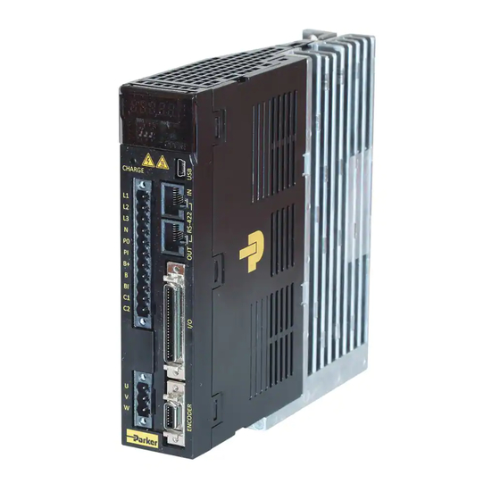
1.1 P Series Products Overview
Overview of P series digital servo drives, features, and motor compatibility.
1.2 Compatible Parker Product
Lists compatible Parker controllers and software for P series drives.
1.3 Assumptions of Technical Experience
Required knowledge for installing and troubleshooting PD drives.
1.4 Technical Support
Information on obtaining technical assistance for PD drive implementation.
2. Mechanical Installation
2.1 Environment
Specifies ambient temperature, humidity, and vibration requirements for PD drive operation.
2.2 Dimensions
Provides detailed dimensions for PD drives and various PM motor series.
2.3 Weight
Lists the weight of PD drives based on housing sizes.
2.4 Mounting Guidelines
Offers advice on cable routing, panel mounting, and avoiding impact for drives.
3. Electrical Installation
3.1 Installation Safety Requirements
Details safety precautions, enclosure recommendations, and ESD protection.
3.2 System Installation Overview
Illustrates components for electrical installation and configuration of PD drives.
3.3 Power Supply
Specifies power circuit electronics, MCCB, noise filter, and DC reactor details.
3.4 Multiple Drive Installations
Explains setting node addresses for multiple drives using rotary and toggle switches.
3.5 Brake Relay (Optional)
Describes dynamic brake functionality and related objects for motor stopping.
3.6 Regeneration Protection
Explains how regeneration protection prevents drive damage from kinetic energy.
3.7 Drive Status Indicators
Details the 7-segment display, operation modes, and alarm/warning codes.
3.8 Connector Descriptions
Provides specifications for power, feedback, analog monitoring, I/O, and motor connectors.
3.9 Installation Test
Outlines steps for testing the drive after installation and configuration.
3.10 Drive Blocks
Presents a block diagram illustrating the PD drive's internal structure and connections.
3.11 Wiring
Details power, feedback, and I/O signal wiring examples and notes.
4. Communications and I/O
4.1 Overview
Explains PD drive compliance with MODBUS-RTU protocol and communication concepts.
4.2 RS-422 Communication
Describes connecting to host controllers via RS-422 for various functions.
4.3 Communication Address Table
Lists parameters, their addresses, and settings for system configuration.
4.4 I/O
Details digital I/O, analog I/O, pulse train, and encoder output signals.
4.5 I/O Signal Setting
Explains allocating digital input and output signals and using user I/O.
5. Tuning
5.1 Servo Tuning Overview
Introduces drive control modes and tuning parameters for torque, speed, and position.
5.2 Position Variable Overview
Explains commanded and actual position variables used in servo systems.
5.3 Servo Response Overview
Discusses system stability, position response types, and performance measurements.
5.4 Automatic Gain Tuning
Describes automatic setting of gains based on load conditions and system rigidity.
5.5 Manual Gain Tuning
Guides tuning speed and position controller gains using a cascade-type approach.
5.6 Vibration Control
Details features for vibration control, including notch filters and inhibition filters.
5.7 Filters
Explains notch filters for removing specific frequency components and adaptive filters.
5.8 Analog Monitor
Describes the 2-channel analog monitor output for gain tuning and status monitoring.
5.9 Gain Conversion
Explains converting between gain groups to optimize system performance.
6. Command Reference
6.1 Pulse Input Position Operation
Details operating pulse input-type position control with a host controller.
6.2 Function Setting of Pulse Input Filter
Explains setting the bandwidth of digital filters for pulse input units to reduce noise.
6.3 Function Setting of PCLEAR
Describes setting the action mode when inputting the position pulse clear (PCLEAR) signal.
6.4 Homing
Details the built-in homing function for returning to origin and related parameters.
6.5 Electronic Gear Setting
Explains the electronic gear function for rotating the motor by user-defined units.
6.6 Speed Control Setting
Covers smooth acceleration/deceleration and servo lock functions for speed control.
6.7 Position Control Setting
Details position command filters and signals related to position control.
6.8 Limit Setting
Explains forward/reverse limit setting, brake output function, and torque limit setting.
6.9 Absolute Encoder Data Transmission
Describes transmitting absolute encoder data upon request via quadrature pulses.
6.10 Touch Probe Function
Explains capturing encoder position using external inputs or index pulse.
7. Procedure
7.1 Procedure Function
Lists auxiliary functions like manual jog, program jog, and resets.
8. Indexer
8.1 Indexer Overview
Introduces Indexing Position and Pulse Input Position modes.
8.2 Indexing Position Operation
Details components of an index, including distance, speed, acceleration, and deceleration.
8.3 Functions of Index Input Signal
Explains functions like Pause, Stop, HSTART, ORG, JSTART, and JDIR.
8.4 Functions of Index Output Signal
Describes EOS and IOUT0-5 signals related to index operation completion.
8.5 Analog Speed Override
Explains overriding index speed using analog input voltage.
9. Object
9.1 Object Dictionary
Defines objects including General, CiA402, Manufacturer Specific, and Index Objects.
10. PM Motors
10.1 Specification
Provides features and specifications for various PM motor series.
10.2 FAL Series N-T Curves
Displays torque-speed curves for FAL series PM motors.
10.3 FBL Series N-T Curves
Displays torque-speed curves for FBL series PM motors.
10.4 FCL Series N-T Curves
Displays torque-speed curves for FCL series PM motors.
10.5 FE Series N-T Curves
Displays torque-speed curves for FE series PM motors.
10.6 FF Series N-T Curves
Displays torque-speed curves for FF series PM motors.
11. Troubleshooting
11.1 Troubleshooting Guidelines
Provides guidance on diagnosing and acting upon abnormalities and errors.
11.2 Servo Alarm and Check List
Lists servo alarms, their descriptions, and corresponding checklist items.
11.3 Servo Warning and Check List
Details servo warnings, their causes, and recommended actions.
Appendix A Firmware Update
Using USB OTG
Explains how to update drive firmware using a USB memory and OTG cable.
Using Drive Support Tool
Describes upgrading drive OS to the latest version via PC using Drive CM software.
Table of Contents
Print
Rename the bookmark
Delete bookmark?
Delete from my manuals?
Login
Sign In
OR
Sign in with Facebook
Sign in with Google
Upload manual
Upload from disk
Upload from URL
Need help?
Do you have a question about the PM-FBL Series and is the answer not in the manual?
Questions and answers