
Related Manuals for AUSTRALIAN MONITOR AMIS ZRM4


Summary of Contents for AUSTRALIAN MONITOR AMIS ZRM4
- Page 1 SERVICE INFORMATION ZRM4 ROUTING MIXER CONTENTS: OPERATION MANUAL SCHEMATIC DIAGRAMS SERVICE BULLETIN Australian Monitor 1 Clyde Street, Silverwater NSW 2128 Australia +61 2 9647 1411 www.australianmonitor.com.au...
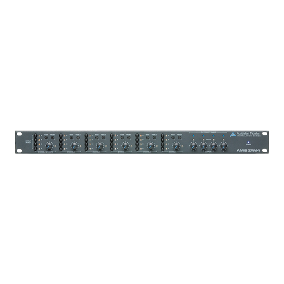
- Page 2 AMIS ZRM4 6 X 4 ROUTING MIXER INSTALLATION AND OPERATION MANUAL...
-
Page 4: Table Of Contents
INTRODUCTION AND CONTENTS The AMIS ZRM4 is an easy to use, yet highly featured 1 RU zone INTRODUCTION routing mixer. It features 6 inputs that can be balanced XLR mic or dual RCA/balanced XLR line level, all of which are available to any FRONT PANEL combination of 4 zone outputs. -
Page 5: Front Panel
Each input has a two stage shelf EQ. indicator. The LED is green when signal is present on the output and LEVEL is red when the signal peak is above Controls the level of the input signal. 0dBu (0.775v). PAGE 4 AMIS ZRM4 INSTALLATION & OPERATION MANUAL... -
Page 6: Rear Panel
NOT be connected to channel #1. OUTPUTS The output XLRs provide balanced line level signals. PAGE 5 AMIS ZRM4 INSTALLATION & OPERATION MANUAL... -
Page 7: Internal Adjustments
XLR input is suitable for use with a balanced line level signal. NOTE: Both MIC/LINE switches must be in the same position for correct operation of the balanced input. The MIC/LINE switches only affect the XLR input. PAGE 6 AMIS ZRM4 INSTALLATION & OPERATION MANUAL... -
Page 8: Basic Setup And Operation
Because of the variation in levels between the possible sources, AMIS ZRM4 offers a number of gain stage adjustments so you can set If the status LED stays red (more than 5% of the time), you should the correct levels for your application. -
Page 9: Advanced Features
NOTE: If using a 500k ohm pot, the connections should be made to the wiper terminal and the anti-clockwise terminal. i.e. max resistance = max volume PAGE 8 AMIS ZRM4 INSTALLATION & OPERATION MANUAL... -
Page 10: Block Diagram
BLOCK DIAGRAM PAGE 9 AMIS ZRM4 INSTALLATION & OPERATION MANUAL... -
Page 11: Specifications
SPECIFICATIONS PAGE 10 AMIS ZRM4 INSTALLATION & OPERATION MANUAL... - Page 12 -26dBu to +4dBu (39mV to 1.23 V) XLR LINE IN -26dBu to +4dBu (39mV to 1.23V) XLR MIC IN -60dBu to -30dBu (0.78mV to 25mV) MAX LEVEL IN >14.1Vrms (+25dBu) MAX LEVEL OUT >15.4Vrms (+26dBu) PAGE 11 AMIS ZRM4 INSTALLATION & OPERATION MANUAL...
- Page 13 AUSTRALIA AND NEW ZEALAND www.australianmonitor.com.au SYDNEY MELBOURNE BRISBANE ADELAIDE PERTH AUCKLAND (NSW & ACT SALES) (VIC & TAS SALES) (QLD SALES) (SA & NT SALES) (WA SALES) (NZ SALES) 149 Beaconsfield 22/277 42 Commercial Road 31 Walsh Street 299 Fitzgerald Street Unit B, 11 Piermark Street Silverwater Middleborough Road...
- Page 14 SW201B MIC/LINE R233 SW201C N.Bus_A D202 PHANTOM R217 R215 D201 R234 N.Bus_B R216 D204 R235 R223 R219 N.Bus_C R236 N.Bus_D IC203 STATUS D203 LM741CN(8) C208 100n Australian Monitor ZRM4 Inputs 1 & 2 Circuit occurs on PCB6335 except where noted...
- Page 15 LEVEL MIC/LINE R433 SW401C N.Bus_A D402 PHANTOM R417 R415 D401 R434 N.Bus_B R416 D404 R435 R423 N.Bus_C R419 R436 N.Bus_D IC403 STATUS D403 LM741CN(8) C408 100n Australian Monitor ZRM4 Inputs 3 & 4 Circuit occurs on PCB6335 except where noted...
- Page 16 SW601B MIC/LINE R633 SW601C N.Bus_A D602 PHANTOM R617 R615 D601 R634 N.Bus_B R616 D604 R635 R623 N.Bus_C R619 R636 N.Bus_D IC603 STATUS D603 LM741CN(8) C608 100n Australian Monitor ZRM4 Inputs 5 & 6 Circuit occurs on PCB6335 except where noted...
- Page 17 100u GP4(3) GP5(2) IC19A gnd(8) X2/6 SW1A PIC12F675 X1/6 X1/4 LM339 100R X2/12 P.Bus_A IC19B X2/8 SW2A Australian Monitor ZRM4 LM339 X2/11 P.Bus_B IC19C X2/7 SW3A LM339 X2/10 Master Output Stage P.Bus_C IC19D X2/5 SW4A LM339 X2/9 P.Bus_D Prioriety Enable (Vox Detect)
- Page 18 On bottom of board IC15 IC14 RH(3) +5(8) X9313 +5(5) V+(4) ADG419 INC(1) IN(6) U/D(2) S1(2) CHIMES D(1) CS(7) S2(8) ALARMS GND(4) RL(6) GND(3) V-(7) Australian Monitor ZRM4 Power Supply & Tone Stage Circuit occurs on PCB6335 except where noted...
- Page 19 Service bulletin Vol. 11 Subject: ZRM4 power supply capacitor Date: 14/11/08 Initial Recipients: Chris Smith, Service, Tech support, David Curtinsmith Model: ZRM4 We have had some failures in the field of the internal ZRM4 SMPS. When a failure occurs it normally destroys the bridge rectifier, SMPS controller, rectifier capacitor and MOSFET’s.
- Page 20 Australian Monitor Service Bulletin ZRM4 Zone Routing Mixer Power Supply Capacitors 20 March 2012 Applicable Models This bulletin applies to ZRM4 Zone Routing Mixers. For Information Only This bulletin is a detailed expansion of a previous bulletin (Vol. 11), originally issued 14 November 2008 and also covers the replacement/upgrade of additional parts.
Need help?
Do you have a question about the AMIS ZRM4 and is the answer not in the manual?
Questions and answers