Rockwell Automation Allen-Bradley 1756-EWEB Installation Instructions Manual
Ethernet/ip web server module
Hide thumbs
Also See for Allen-Bradley 1756-EWEB:
- Installation instructions manual (76 pages) ,
- User manual (70 pages) ,
- User manual (32 pages)
Table of Contents
Advertisement
Quick Links
Download this manual
See also:
User Manual
EtherNet/IP Web Server Module
Catalog Number 1756-EWEB
Use this manual as a guide to install the EtherNet/IP
Note that this document covers hardware installation and some configuration
procedures to get you started. Refer to the EtherNet/IP Web Server Module User
Manual, publication number ENET-UM527, for more detailed configuration
information.
The following table lists the contents of this document and where to find
specific information.
Topic
Important User Information
Environment and Enclosure
Preventing Electrostatic Discharge
European Hazardous Location Approval
North American Hazardous Location Approval
Identify Module Components
Prepare the Chassis for Module Installation
Determine Module Slot Location
Install the Module
Using the Web Server Module
Troubleshooting the Module
Where to Find More Information on Configuring the Module
Specifications
Rockwell Automation Support
Installation Instructions
®
Publication
1756-IN588A-EN-P - February 2004
Web Server Module.
See Page
2
2
4
4
5
8
9
10
11
19
25
26
27
30
Advertisement
Table of Contents

Related Manuals for Rockwell Automation Allen-Bradley 1756-EWEB


Summary of Contents for Rockwell Automation Allen-Bradley 1756-EWEB
- Page 1 Identify Module Components Prepare the Chassis for Module Installation Determine Module Slot Location Install the Module Using the Web Server Module Troubleshooting the Module Where to Find More Information on Configuring the Module Specifications Rockwell Automation Support Publication 1756-IN588A-EN-P - February 2004...
-
Page 2: Important User Information
In no event will Rockwell Automation, Inc. be responsible or liable for indirect or consequential damages resulting from the use or application of this equipment. -
Page 3: Environment And Enclosure
EtherNet/IP Web Server Module 3 Environment and Enclosure This equipment is intended for use in a Pollution Degree 2 industrial environment, in overvoltage Category II applications (as defined in IEC publication 60664-1), at altitudes up to 2000 meters without derating. This equipment is considered Group 1, Class A industrial equipment according to IEC/CISPR Publication 11. -
Page 4: Preventing Electrostatic Discharge
4 EtherNet/IP Web Server Module Preventing Electrostatic Discharge This equipment is sensitive to electrostatic discharge, ATTENTION which can cause internal damage and affect normal operation. Follow these guidelines when you handle this equipment: • Touch a grounded object to discharge potential static. -
Page 5: North American Hazardous Location Approval
EtherNet/IP Web Server Module 5 Compliance with the Essential Health and Safety Requirements has been assured by compliance with EN 50021. When using this equipment, consider the following: IMPORTANT • This equipment is not resistant to sunlight or other sources of UV radiation. •... -
Page 6: Explosion Hazard
6 EtherNet/IP Web Server Module investigation by the local Authority Having Jurisdiction at the time of installation. EXPLOSION HAZARD WARNING • Do not disconnect equipment unless power has been removed or the area is known to be nonhazardous. • Do not disconnect connections to this equipment unless power has been removed or the area is known to be nonhazardous. -
Page 7: Risque D'explosion
EtherNet/IP Web Server Module 7 du système. Les combinaisons d'équipements dans le système sont sujettes à inspection par les autorités locales qualifiées au moment de l'installation. RISQUE D’EXPLOSION AVERTISSEMENT • Couper le courant ou s’assurer que l’environnement est classé non dangereux avant de débrancher l’équipement. -
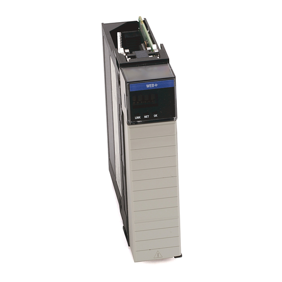
Page 8: Identify Module Components
8 EtherNet/IP Web Server Module Identify Module Components Use the following figure to identify the external features of the 1756-EWEB module. Backplane MAC ID Label (may be inside here or Front View Side View Connector at bottom as shown below) Web + Front Panel... -
Page 9: Prepare The Chassis For Module Installation
EtherNet/IP Web Server Module 9 Prepare the Chassis for Module Installation Before you install the module, you must install and connect a ControlLogix chassis and power supply. 1756-A4 Power Chassis Supply 20805-M For information on installing these products, refer to the publications listed in the following table. -
Page 10: Determine Module Slot Location
10 EtherNet/IP Web Server Module Determine Module Slot Location You can install the module in any slot in the ControlLogix chassis. You can also install multiple 1756-EWEB modules in the same chassis. The figure below shows chassis slot numbering in a 4-slot chassis. Slot 0 is the first slot and is always the left-most slot in the rack (the first slot to the right of the power supply). -
Page 11: Install The Module
EtherNet/IP Web Server Module 11 Install the Module Align the circuit board with top and bottom guides in the chassis. Circuit Board 31275-M Slide the module into the chassis. Make sure the module backplane connector properly connects to the chassis backplane. The module is properly installed when it is flush with the power supply or other installed modules. - Page 12 12 EtherNet/IP Web Server Module Removing or Replacing the Module (when applicable) Push on upper and lower module tabs to disengage them. 31277-M 31278-M Slide module out of chassis. If you are replacing an existing module with an identical IMPORTANT one, and you want to resume identical system operation, you must install the new module in the same slot.
- Page 13 EtherNet/IP Web Server Module 13 Installing or Removing the Module Under Power This module is designed to be installed or removed while chassis power is applied. When you insert or remove the module while backplane WARNING power is on, an electrical arc can occur. This could cause an explosion in hazardous location installations.
- Page 14 14 EtherNet/IP Web Server Module Connect the Module to the EtherNet/IP Network If you connect or disconnect the communications WARNING cable with power applied to this module or any device on the network, an electrical arc can occur. This could cause an explosion in hazardous location installations.
- Page 15 EtherNet/IP Web Server Module 15 We recommend connecting the module to the IMPORTANT network via a 100MB EtherNet/IP switch, which will reduce collisions and lost packets and increase network bandwidth. For detailed EtherNet/IP connection information, see the following publications: • EtherNet/IP Performance and Application Guide, publication ENET-AP001 •...
- Page 16 16 EtherNet/IP Web Server Module Check Power Supply and Module Status Check the LED indicators and alphanumeric display to determine if the power supply and module are operating properly. Web + Alphanumeric Display LINK NET OK LINK OK indicator is red during self-test, then green.
- Page 17 EtherNet/IP Web Server Module 17 Obtain an IP Address By default, the web server module is DHCP enabled. If you connect the web server module to a network that has a DHCP server, that server will assign a dynamic IP address to the web server module and the four-digit display on the front of the web server module will display each of the four numbers of the IP address.
- Page 18 18 EtherNet/IP Web Server Module Log Into the Module Many of the features of the web server module require you to log in with appropriate access. If you select a feature, such as New Data View, the web server module prompts you to enter your user name and password. The default user name is “Administrator”...
-
Page 19: Using The Web Server Module
EtherNet/IP Web Server Module 19 Confirm the Network Configuration On the Administrator Settings → Device Configuration → Network Configuration page, you can verify the IP address and other network settings. For more information, see the EtherNet/IP Web Server Module User Manual, publication ENET-UM527. - Page 20 20 EtherNet/IP Web Server Module Create a Data View Before you can create a data view in the web server, the tags you want to view must exist in the controller that is local (in the same chassis) to the web server module.
- Page 21 EtherNet/IP Web Server Module 21 3. Click on the Add button to add the tag to the data view Continue adding as many tags as you want to configure. 4. Click Create View. 5. From the Data Views → Data View page, select the data view you just created.
- Page 22 22 EtherNet/IP Web Server Module Note: To change a data value, you need Administrator or Write access. For more information, see the EtherNet/IP Web Server Module User Manual, publication ENET-UM527A. Configure Email You configure the SMTP server that manages email on the Administrative Settings →...
- Page 23 EtherNet/IP Web Server Module 23 Configure the Time Server You select the method the web server module uses to maintain an accurate date and time stamp on the Administrative Settings → Server Management → Time Settings page. This makes sure that files you save to the web server module have accurate date and time stamps.
- Page 24 24 EtherNet/IP Web Server Module Enable/Disable Other Services You can enable other services from the Administrative Settings → Device Configuration → Device Services page. Select the services you want to use. Enable the: • FTP (File Transfer Protocol) service to allow file transfers to and from the web server module •...
-
Page 25: Troubleshooting The Module
EtherNet/IP Web Server Module 25 Troubleshooting the Module If the alphanumeric display and LED indicators do not sequence through the expected states refer to the following troubleshooting tables. The three bi-color (red/green) LED status indicators on the 1756-EWEB module provide diagnostic information about the module and its connections to the network. -
Page 26: Where To Find More Information On Configuring The Module
26 EtherNet/IP Web Server Module Link Status Indicator The Link Status LED provides the following information: State Status Description No data transmission Module is not ready to communicate. Green Ready Module is ready to communicate. Flashing Green Data transmission in Module is communicating over the progress network. -
Page 27: Specifications
EtherNet/IP Web Server Module 27 Specifications Specification: Value: Module Location Any slot in the ControlLogix chassis Maximum Backplane 700mA @ 5.1V DC Current Load 3mA @ 24V DC from I/O chassis backplane Power Dissipation 3.65W maximum Isolation voltage (continuous-voltage withstand rating) Operational Temperature IEC 60068-2-1 (Test Ad, Operating Cold), IEC 60068-2-2 (Test Bd, Operating Dry Heat),... - Page 28 28 EtherNet/IP Web Server Module Specification: Value: ESD Immunity IEC 61000-4-2: 6kV contact discharges 8kV air discharges Radiated RF Immunity IEC 61000-4-3: 10V/m with 1kHz sine-wave 80%AM from 30MHz to 1000MHz 10V/m with 200Hz 50% Pulse 100%AM at 900Mhz EFT/B Immunity IEC 61000-4-4: ±2kV at 5kHz on communications ports Surge Transient Immunity...
- Page 29 See the Product Certification link at www.ab.com for Declarations of Conformity, Certificates, and other certification details. ControlLogix and RSLogix are trademarks of Rockwell Automation. EtherNet/IP is a registered trademark of Digital Equipment Corporation, Intel and Xerox. This product incorporates code from GoAhead Software, Inc., Copyright 2004 GoAhead Software, Inc.
-
Page 30: Rockwell Automation Support
(see phone number above to obtain one) to your distributor in order to complete the return process. Outside United States Please contact your local Rockwell Automation representative for return procedure. Publication 1756-IN588A-EN-P - February 2004 PN 957824-76 Copyright © 2004 Rockwell Automation, Inc. All rights reserved. Printed in the U.S.A.
Need help?
Do you have a question about the Allen-Bradley 1756-EWEB and is the answer not in the manual?
Questions and answers