CAB A8 Service Manual
Hide thumbs
Also See for A8:
- Operator's manual (134 pages) ,
- Service manual (119 pages) ,
- Configuration instructions (68 pages)
Table of Contents
Advertisement
Quick Links
Download this manual
See also:
Operator's Manual
Advertisement
Table of Contents

Related Manuals for CAB A8


Summary of Contents for CAB A8
- Page 1 Transferdrucker / Transfer Printer Serviceanleitung / Service Manual Ausgabe /Edition 2/00...
- Page 2 Fax : +1 330-225-0099 Web : http://www.cabgmbh.com e-mail : info@cabgmbh.com copyright by cab / 900 8162 / K11 / 50 Technische Änderungen vorbehalten In accordance with our policy of continual product improvement, we reserve the right to alter specifications without notice...
-
Page 3: Table Of Contents
5.3 Replacing the print roller and rewind assist roller ..29 5.4 Wechsel der Etikettenlichtschranke ......31 5.4 Replacing the label edge sensor ....... 31 5.5 Wechsel der Leiterplatte A8 ........32 5.5 Replacing the PCB A8 ..........32 5.6 Wechsel der Rutschkupplungen ....... 34 5.6 Replacing the slipping clutches ........ - Page 4 7.3 Permanent angezeigte Hardwarefehler ..... 50 7.3 Permanently displayed hardware errors ....50 Funktionsbeschreibung Elektronik Functional description 8.1 Leiterplatte A8, kpl. (Art.-Nr. 553 9294) ....51 8.1 PCB A8, kpl. (Art.-Nr. 553 9294) ......51 8.2 Bedienfeld ..............51 8.2 Control panel ............51 8.3 Sensoren ..............
-
Page 5: Einführung
Es beinhaltet technische Informationen, die sich auf die The technical information included relates to hardware and Hardware und den mechanischen Teil des Etikettendruckers mechanical parts of the A8 Label Printer. A8 beziehen. Informationen zur Bedienung des Druckers finden Sie in der Information related to the printer's operation will be found Bedienungsanleitung. -
Page 6: Allgemeine Sicherheitshinweise
1.3 Allgemeine Sicherheitshinweise 1.3 General safety instructions Beachten Sie die folgenden Regeln zur Follow the general safety rules below: allgemeinen Sicherheit: Ÿ Keep the area around the device clean at all times! Ÿ Halten Sie die Umgebung des Gerätes während und nach Ÿ... -
Page 7: Sicherheit Beim Umgang Mit Elektrizität
1.4 Sicherheit beim Umgang mit 1.4 Safe handling of electricity Elektrizität Beachten Sie beim Umgang mit Elektrizität folgende Follow the additional instructions below when handling zusätzliche Regeln: electricity: Ÿ Stellen Sie die Lage vom Not- oder Netzschalter fest, um Ÿ Find out the positions of the emergency and the power ihn im Notfall schneller bedienen zu können! switch in order to operate them quickly in an emergency Ÿ... -
Page 8: Leistungsmerkmale
1.5 Leistungsmerkmale 1.5 Features Der Etikettendrucker A8 ist ein Thermo-/Thermo- The A8 Label Printer is a direct thermal and thermal transfer transferdrucker mit folgenden Eigenschaften: printer offering the following features: Ÿ langlebig, für den dauerhaften Industrieeinsatz konzipiert Ÿ long lifetime, intended for permanent industrial use Ÿ... -
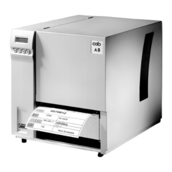
Page 9: Teile Des Etikettendruckers
1.7 Teile des Etikettendruckers 1.7 Printer Component Location Bild 1 Vorderansicht A8 Figure 1 Front view A8 1 Deckel 1 Cover 2 Display 2 Display 3 Funktionstasten mit LED 3 Function keys with LED 4 Abreißkante 4 Tear-off plate 5 Peripherieanschluss... - Page 10 Bild 3 1 Deckel Figure 3 1 Cover 2 Abwickler Transfer 2 Ribbon supply hub 3 Aufwickler Transfer 3 Ribbon take up hub 4 Druckkopf 4 Printhead 5 Druckwalze 5 Print roller 6 Abreißkante 6 Tear-off plate 7 Rändelschraube 7 Knurled screw 8 Flansch 8 Flange 9 Schwenkhebel...
-
Page 11: Optionen
1.8 Optionen 1.8 Optional features Zur Erweiterung der Einsatzmöglichkeiten des Etiketten- The optional features below are available for the A8 Label druckers A8 stehen die folgenden Optionen zur Verfügung: Printer: Ÿ Externer Aufwickler Ÿ External Rewinder Ÿ Schneidmesser Ÿ Cutter Assembly Ÿ... -
Page 12: Technische Daten
1.9 Technische Daten 1.9 Technical Specifications Druckprinzip: Thermo-/Thermotransferdruck Type: Thermal-/Thermal transfer printer Druckkopf: Dünnfilm-Transferkopf Printhead: Thin film transfer head Druckkopf- Printhead auflösung: 203 dpi = 8 Punkte/mm Resolution: 203 dpi = 8 dots/mm Anzahl der Punkte/Zeile: 1728 Dots/Line: 1728 Druckbreite: 216 mm Printing width: 8.5"... - Page 13 Eindimensionale Codes für den Handel: one-dimensional codes for the EAN-8, EAN-13, EAN-128, EAN/UCC trade: 128, EAN/UPC Anhang 2, EAN-8, EAN-13, EAN-128, EAN/UCC EAN//UPC Anhang 5, JAN-8, JAN-13, 128, EAN/UPC Anhang 2, UPC-A, UPC-E EAN//UPC Anhang 5, JAN-8, JAN-13, UPC-A, UPC-E Zweidimensionale Codes: Data Matrix, PDF317, MicroPDF, two-dimensional codes:...
- Page 14 Material- Durchlichtsensor Material Gap sensor (see-through), Bottom- erkennung: Reflexlichtsensor von unten recognition: reflective sensor, Distance to paper edge: 12 to 2 in Abstand zur (3 bis 52 mm) Anlegekante: 3 bis 52 mm Transfer ribbon: Length: max. 17.7 in Transferband: Länge: 450 m (450 m)
-
Page 15: Selbsttest
Selbsttest Self test Der Etikettendrucker A 8 hat einen eingebauten Selbsttest. The A 8 Label Printer has a built-in self test, which makes Dieser erleichtert die Fehlersuche und gibt Aufschluss über troubleshooting easier and gives information about the die Voreinstellungen des Gerätes. default configuration of the device. -
Page 16: Erklärung Des Selbsttests
2.3 Erklärung des Selbsttests 2.3 Self test explanation Bild 4 Selbsttestausdruck Figure 4 Self test printout 1 Setup-Statusinformationen 1 Setup and Status information 2 Schriftarten 2 Availiable character sets 3 Testmuster 3 Test pattern 4 Firmware-Version 4 Firmware version 5 Barcode mit Testinformationen 5 Bar code with test information... -
Page 17: Internes Setup
Internes Setup Internal Setup Der Drucker besitzt ausser dem für den Bediener zugäng- Apart from the setup facilities that can be accessed by the lichen Setup (siehe Bedienungsanleitung) ein internes Setup, user (see manual), the printer has an internal setup which is das ausschließlich dem Service vorbehalten ist. -
Page 18: 2) Druckkopf - Testmuster
3.2 2) Druckkopf - Testmuster 3.2 2) Printhead test pattern Dieser Programmteil unterstützt die mechanische Justage This part of the Internal Setup supports the printhead des Druckkopfes. Hierzu wird im 5-Sekundentakt ein alignment. There will be a grid test pattern printed every 5 Gittermuster von 50 mm Länge gedruckt. -
Page 19: 5) Transferband- Und Etikettenlichtschranke Abgleichen
This will be necessary when one of both bzw. Etikettenlichtschranke abzugleichen. Dies wird nötig, sensors or the PCB A8 have been replaced. The adjustment wenn eine der Lichtschranken selbst oder die Leiterplatte process always includes the adjustments of both sensors. - Page 20 Using 1/256:246 Using 2/256:233 Using 3/256:218 Using 4/256:199 Using 5/256:180 Using 6/256:158 Using 7/256:133 Using 8/256:108 Using 9/256:83 Using 10/256:58 Using 11/256:36 Please insert label liner (any key) Während des Abgleichs wird der Strom der Sensordiode so During the sensor adjustment the current of the diode is lange erhöht, bis die Messwerte am Empfängertransistor increased until the measuring value at the transistor (number (Zahl hinter dem Doppelpunkt) ein bestimmtes Niveau...
-
Page 21: 7) Druckorientierung
3.6 7) Druckorientierung 3.6 7) Print adjustment Dieser Programmpunkt wurde für Spezialanwendungen in This program part to be used for special applications was das interne Setup aufgenommen. Durch Betätigen der Taste included in the internal setup. By entering „7“ you can shift „7”... -
Page 22: A) Spendeverzögerung
3.8 A) Spendeverzögerung 3.8 A) Delay for peel-off Bei eingeschalteter Spendeverzögerung wartet der Drucker When peel-off is active, the printer waits in peel-off mode im Spendemodus ca. 250 ms, bevor das Etikettenmaterial for approx. 250 ms after the label has peeled off, before nach Entnahme des gespendeten Etiketts zurückgezogen retracting the media. -
Page 23: P) Pin Für Setup-Schutz Setzen
3.10 P) PIN für Setup-Schutz setzen 3.10 P) Set PIN for setup protection Um eine unkontrollierte Setup-Änderung zu verhindern, To avoid an unauthorized setup changing it is possible to kann eine Code-Nummer vereinbart werden, die beim Start install a PIN that is required for starting the user setup. des Bediener-Setup abgefragt wird. -
Page 24: Wartung
Wartung Maintenance 4.1 Allgemeine Reinigung 4.1 General cleaning Innen: Während des Betriebs können sich um die Interior: During normal operation, media debris may Druckermechanik Staubpartikel ansammeln. accumulate around the printer mechanism. Entfernen Sie diese Staubpartikel regelmäßig Clean away this debris regularly using a soft mit einem weichen Pinsel und/oder einem bristle brush and/or vacuum cleaner. -
Page 25: Reinigen Der Druck- Und Umlenkwalzen
4.3 Reinigen der Druck- und Umlenk- 4.3 Cleaning the print and guide walzen rollers Wenn die Druck- und Umlenkwalzen durch Staub, Leim- If the print and guide rollers become contaminated with dirt, reste oder Farbpartikel verunreinigt werden, kann die label adhesive or ink, print quality may also be adversely Druckqualität ebenfalls beeinträchtigt werden. -
Page 26: Wechsel Von Baugruppen
For servicing the A 8 printer, the following set of tools is Satz an Werkzeugen: recommended: 1. Sonderwerkzeuge (cab-Eigenfertigung): 1. cab special tools: - Prüfkörper (Art.-Nr. 553 4199) - Test collar (Art. No. 553 4199) - Prüfkörper (Art.-Nr. 553 9223) - Test collar (Art. - Page 27 - Seegerringzange ZGG 0 - Snap ring pliers ZGG 0 - Seegerringzange ZGG 1 - Snap ring pliers ZGG 1 - Seitenschneider 130 mm - Diagonal cutters 5.12 in/130 mm - Papierschere - Scissors - Pinzette - Tweezers - Fühllehre, 13tlg. (0,05 steigend) - Feeler gauge, 13 pcs, (increasing by steps...
-
Page 28: Wechsel Des Druckkopfes Und Des Druckkopfkabels
5.2 Wechsel des Druckkopfes und 5.2 Replacing the printhead and des Druckkopfkabels the printhead cable ACHTUNG! CAUTION! Sachschäden durch elektrostatische Ground yourself to the chassis before Aufladung! Erden Sie sich vor dem you remove or install the printhead. This Entfernen oder dem Einbau des Druck- will prevent a static discharge from your kopfes am Gehäuse. - Page 29 ACHTUNG! CAUTION! Oberfläche des Druckkopfes nicht Handle new printhead carefully to avoid zerkratzen! Positionierungsstifte scratching! Positioning pins must snap müssen bei Montage beidseitig in on both sides ! einrasten! 8. Carefully slide the head plate with the printhead onto 8. Kopfplatte mit Druckkopf in die Positionierstifte the positioning pins.
- Page 30 7. Kabel aus den Kabelhaltern (1, Bild 5) und (11) 7. Pull the defective cable out of the clamps (1) and (11). herausnehmen. 8. Remove the plug (10 or 12) from the PCB A8. 8. Stecker (10) oder (12) von der Leiterplatte A8 abhebeln.
-
Page 31: Wechsel Der Druckwalze Und Umlenkwalze
5.3 Wechsel der Druckwalze und 5.3 Replacing the print roller and Umlenkwalze rewind assist roller WARNUNG! WARNING! Lebensgefahr durch Strom- Mortal danger by electric shock! schlag! Netzstecker ziehen! Unplug power cord! Wechsel Druckwalze: Replacing print roller: 1. Deckel öffnen, Druckkopf hochklappen, Etiketten und 1. - Page 32 8. Druckkopf mit Hebel (12) öffnen und 8. Open the printhead using the lever (12) and swing the Versteifung (13) nach unten klappen. plate (13) downwards. 9. Sicherungsring (15) von der Achse (14) abnehmen. 9. Remove the E-ring (15) from the axle (14). 10.
-
Page 33: Wechsel Der Etikettenlichtschranke
2. Gehäuse abschrauben. 3. Remove the plug (1) of the label sensor cable from the 3. Stecker (1) des Kabels der Etikettenlichtschranke PCB A8. von der Leiterplatte abziehen. 4. Open the cable clamps (2) and (3) and pull the label 4. -
Page 34: Wechsel Der Leiterplatte A8
Kabelstecker aufstecken. 8. Check firm seat of all plugs on the PCB as well as 8. Festen Sitz aller Stecker auf der Leiterplatte A8 und the seat of the PCB A8 and the Centronics plug. die Befestigung von Leiterplatte und Centronics- 9. - Page 35 5.6 Wechsel Rutschkupplungen 5.6 Replacing the slipping clutches WARNUNG! WARNING! Lebensgefahr durch Strom- Mortal danger by electric shock! schlag! Netzstecker ziehen! Unplug power cord! Die Aufwickler für Transferband und Etiketten sind mit The take up hubs for labels and transfer ribbon are coupled Rutschkupplungen in den Hauptantrieb eingekoppelt.
-
Page 36: Wechsel Der Rutschkupplungen
Vorarbeiten für den Wechsel der Kupplungen des Preparation for the replacement of the slipping clutches Etikettenaufwicklers und des Transferbandaufwicklers: at the label take up hub and the ribbon take up hub: Die Vorbereitungen für den Wechsel dieser Kupplungen The preparation for the replacements of these two clutches erfolgen in analoger Weise. - Page 37 Wechsel der Rutschkupplungen: Clutch replacement : 1. Rändelmutter (1) abschrauben und dabei auf die 1. Unscrew the knurled nut (1). Make sure that the 6 Federn (3) achten. Federn aufnehmen und ablegen. springs (3) do not get lost. 2. Zwei Gewindestifte (2) lösen und 2.
-
Page 38: Justagen, Einstellungen Und Abgleiche
Justagen, Einstellungen Alignings and Adjustings Abgleiche 6.1 Justage des Druckkopfes 6.1 Aligning the printhead Zur Erzielung eines optimalen Druckbildes ist die Heizzeile For optimum print quality, the line of heating elements on des Druckkopfes exakt zur Druckwalze auszurichten. Diese the printhead must be parallel and aligned correctly to the Justage wird bei der Inbetriebnahme werksseitig vorgenom- print roller. - Page 39 Bild 15 1 Justageschrauben Figure 15 1 Aligning screws 2 Feststellschraube für Druckkopf 2 Locking screw 3 Versteifung 3 Plate...
-
Page 40: Einstellung Der Druckkopfabstützung
6.2 Adjusting the printhead support 6.2 Einstellung der Druckkopfab- stützung CAUTION! Wear of the printhead! ACHTUNG! Danger of early wear of the printhead if Druckkopfverschleiß! there is a continuous contact between Vorzeitiger Verschleiß des Druckkopfes printhead and print roller. Avoid direct bei ständiger direkter Berührung zwi- contact of print head and print roller by schen Druckkopf und -walze! -
Page 41: Einstellung Des Druckkopfandruckes
6.3 Einstellung des Druckkopfandruckes 6.3 Adjusting the printhead pressure HINWEIS! NOTICE! Die Messung des Druckkopfandruckes Perform the measuring of the printhead muss bei deaktivierter Druckkopfab- pressure when the printhead support is stützung durchgeführt werden! deactivated! Die Messung erfolgt indirekt in den Randbereichen des The printhead pressure is measured indirectly at both ends Druckkopfes. -
Page 42: Justage Des Transferbandlaufes
6.4 Justage Transferbandlauf 6.4 Aligning the transfer ribbon feed Wenn im Lauf der Transferbandes Faltenbildungen auftre- If creases, lines or black patches appear in the print image ten, die zu Druckbildfehlern führen, kann die Umlenk- resulting in a poor print quality, this may be caused by achse (1) zur Korrektur des Fehlers verstellt werden. - Page 43 Messung am Transferbandabwickler: Measuring the torque at the ribbon supply hub: Die Messung des Moments erfolgt über die Bestimmung der The torque is measured by determining the traction using a Zugkraft an einem auf den Wickler aufgesteckten Prüf- test collar (Part. No. 553 4199) at the supply hub. körper (Artikel-Nr.
- Page 44 Messung am Transferbandaufwickler: Measuring the torque at the ribbon take up hub: Die Messung des Moments erfolgt über die Bestimmung der The torque is measured by determining the traction using a Zugkraft an einem auf den Wickler aufgesteckten Prüf- test collar (Part. No. 553 4199) at the supply hub. körper (Artikel-Nr.
- Page 45 Messung am Etikettenabwickler: Measuring the torque at the media supply hub: Die Messung des Moments erfolgt über die Bestimmung der The torque is measured by determining the traction using a Zugkraft an einem auf den Wickler aufgesteckten Prüf- test collar (Part. No. 553 9223) at the supply hub. körper (Artikel-Nr.
- Page 46 Messung am internen Aufwickler: Measuring the torque at the internal rewinder: Die Messung des Moments erfolgt über die Bestimmung der The torque is measured by determining the traction using a Zugkraft an einer direkt auf den Aufwickler befestigten tstring with is wound around the rewinder. Schnur.
-
Page 47: Abgleich Der Transferbandlichtschranke
6.6 Abgleich der Transferbandlicht- 6.6 Adjusting the Transfer Ribbon Sensor schranke The transfer ribbon sensor is adjsuted by using the internal Der Abgleich der Transferbandlichtschranke erfolgt über setup (chapter 3.5). das interne Setup (siehe Abschnitt 3.5). 6.7 Adjusting the Label Edge Sensor 6.7 Abgleich der Etikettenlichtschranke The label edge sensor is adjsuted by using the internal Der Abgleich der Etikettenlichtschranke erfolgt über das... -
Page 48: Fehlersuche Und Fehlerbeseitigung
3. Label edge sensor is not schmutzt, reinigen 3. Etikettenlichtschranke nicht adjusted (f.e. after replacing the abgeglichen (z.B. nach Wechsel PCB A8); carry out the adjust- ment. der Leiterplatte); Lichtschranke abgleichen 4. label edge sensor defective, replace sensor 4. - Page 49 Symptom Ursache und Lösung Symptom Cause and solution Drucker druckt Folge 1. Drucker im Monitormodus; Printer prints 1. Printer in monitor (ASCII sequence of characters von Zeichen anstelle Abbruch des Monitormodus dump) mode; quit this mode des Etikettenformats instead of label format mit Taste by pressing the key.
-
Page 50: Ausfall Von Gerätefunktionen
Defekt power module. Austausch Trafo, Netzmodul 3. 5V auf Leiterplatte A8 prüfen; LED3 3. Check 5V on PCB A8; LED3 (green) (grün) muss leuchten must be switched on positiv: -> 6. LED 3 on : -> 6. - Page 51 Replace cable connector if necessary positiv: -> 3. negativ: Kabel tauschen 3. Check peripherial device 3. Überprüfung des Peripheriegerätes Repair or replace peripherial device if positiv: Wechsel der LP A8 defective. negativ: Reparatur des Peripherie- gerätes 4. Replace PCB A8...
-
Page 52: Permanent Angezeigte Hardwarefehler
7.3 Permanently displayed hardware fehler errors Fehlermeldung Ursache und Lösung Error Cause and Solution A/D-Wandler defekt Fehler der Leiterplatte A8, ADC malfunction Error of PCB A8; LP austauschen replace PCB dRAM defekt Fehler der Leiterplatte A8, dRAM malfunction Error of PCB A8;... -
Page 53: Funktionsbeschreibung Elektronik
Funktionsbeschreibung Functional description Elektronik 8.1 Leiterplatte A8, kpl. (Art.-Nr. 5539294) 8.1 Mainboard A8 (Part. No. 5539294) Die komplette Logik sowie die Stromversorgung des Druk- The complete logic and the power supply are carried by this kers ist auf dieser Leiterplatte untergebracht. Es gibt folgen- PCB. -
Page 54: Pc Card-Anschluss
8.4 PC Card-Anschluss 8.4 PCMCIA board Der Anschluss dient der Aufnahme von Speicherkarten This connector can be used to accomodate memory cards nach PCMCIA 2.0. Es sind sowohl sRAM, als auch Flash- according to PCMCIA 2.0. Both sRAMs as well as Flash Karten benutzbar, soweit diese eine CIS beinhalten. -
Page 55: Anlagen Ersatzteilliste
When ordering spare parts, please note the following: 1. Ersatzteilbestellungen richten Sie bitte an die folgende 1. Please address spare parts orders to: Adresse: Tharo Systems, Inc. cab-Produkttechnik cab-Produkttechnik GmbH GmbH P.O. Box 798 Postfach 1904 Postfach 1904 Brunswick, Ohio 44212... - Page 56 Index 1 00-02-29 Nr. Artikel-Nr. Benennung Stück 553 9385 Gehäuse, kpl. 590 2032 Linsenschr. DIN7985-M4x6-4.8-H-galZn 590 3003 Scheibe DIN125-A4.3-galZn 553 9294 Leiterplatte-bestückt A8 590 2026 Linsenschr. DIN7985-M3x6-8.8-H-galZn 553 9352 Blende 590 2129 EJOT-PT-Schraube KB22x6-WN1412-galZn-cB 553 9349 LCD-Anzeige, kpl. 23/8x 553 9368 LP Tastatur, best.
- Page 57 Anlage A Index 1 00-02-29 Nr. Artikel-Nr. Benennung Stück 590 1574 Kabelhalter ACC38-A Panduit 590 2353 Flachkopfschr. m. A. DIN923-M4x8-galZn 590 2501 Sechskantmutter DIN934-M4-8-galZn 590 3003 Scheibe DIN125-A4.3-galZn 553 9325 Träger, kpl. 590 2144 Zylinderschr. DIN7984-M3x5-8.8-galZn 553 9323 Stütze 553 9811 Kopfschraube 553 0362 Druckschraube...
- Page 58 Anlage A Index 1 00-02-29 Nr. Artikel-Nr. Benennung Stück 590 5495 Zahnriemen 205MXL037 590 5565 Zahnriemen 260MXL037 590 3525 Sicherungsscheibe DIN6799-4-galZn 553 9861 Riemenrad 30, kpl. 553 9337 Achse 590 3519 Sicherungsscheibe DIN6799-6-galZn 553 9271 Rolle 553 9214 Spannblech, kpl. 590 2048 Zylinderschr.
- Page 59 Anlage A Index 1 00-02-29 Nr. Artikel-Nr. Benennung Stück 591 7298 Sicherungshalter 6.3x32 RSH0031.6001 590 2005 Zylinderschraube DIN912-M3x8-8.8-galZn 591 6941 Sicherung 6.3x32 T12A 590 2505 Sechskantmutter DIN934 M3-8-galZn 590 2510 Sechskantmutter DIN934-M4-Ms-galNi 590 3011 Zahnscheibe DIN6797-A4.3-galZn 590 3033 Scheibe DIN125-A4.3-Ms-galNi 553 4729 Schutzleiter 590 2252...
- Page 60 Anlage A Index 1 00-02-29 Nr. Artikel-Nr. Benennung Stück 590 2018 Zylinderschraube DIN912-M3x16-8.8-galZn 590 3004 Scheibe DIN125-A3.2-galZn 553 9292 Sensor Transferband 590 2256 Flachkopfschr. m.A.DIN923-M4x12-5.8-galZn 553 9355 Sensorblech, kpl. 553 3968 Mehrscheibenkupplung, Teil 1 590 3516 Sicherungsring DIN471-8-galZn 590 3020 Passscheibe DIN988-8x14x0,5 553 9216 Anschlag...
- Page 61 Anlage A Index 1 00-02-29 Nr. Artikel-Nr. Benennung Stück 553 9270 Abwickelachse, kpl. 590 2240 Senkschraube DIN7991 M5x14-8.8-galZn 553 9804 Zugfeder A8 553 9265 Schwenkhebel, mont. 590 2224 Senkschraube DIN7991 M4x12-8.8-galZn 553 9800 Teller 891 0053 Vierkantmutter M4 8mm 590 2034 Linsenschraube DIN7985-M4x8-4.8-H-galZn...
- Page 62 Anlage A Index 1 00-02-29 Nr. Artikel-Nr. Benennung Stück 590 3516 Sicherungsring DIN471-8-galZn 590 3053 Passscheibe DIN988-8x14x0.1 15/3x 590 2002 Zylinderschraube DIN912-M4x10-8.8-galZn 553 9240 Lager, kpl. 16/3x 553 3969 Mehrscheibenkupplung Teil 1 553 9846 Zahnrad 42-HK, kpl. 590 3043 Passscheibe DIN988-10x16x0,2 590 3527 Sicherungsring DIN471-10 553 9809...
- Page 63 Anlage A Index 2 00-03-30 Nr. Artikel-Nr. Benennung Stück 590 1059 Nyliner 1320-505-00 553 9311 Umlenkwelle 553 9305 Umlenkwelle Apo 8 590 2017 Zylinderschraube DIN912-M4x16-8.8-galZn 553 9306 Umlenkachse Apo 8 590 2133 Senkschraube DIN965-M4x10-4.8-H-galZn 553 4450 Etikettenlichtschranke 553 9308 Abstandshülse 553 4487 Anschlag 590 2293...
- Page 64 Anlage A Index 1 00-02-29 Nr. Artikel-Nr. Benennung Stück 590 2085 Linsenschraube DIN7985-M3x4-4.8-H-galZn 553 9807 Kabelkasten 590 2017 Zylinderschraube DIN912-M4x16-8.8-galZn 553 9304 Winkel - Kopf 590 2133 Senkschraube DIN965-M4x10-4.8-H-galZn 590 2017 Zylinderschraube DIN912-M4x16-8.8-galZn 553 9851 Lagerprofil, kpl. 553 0361 Schieber 590 2133 Senkschraube DIN965-M4x10-4.8-H-galZn 553 9309...
-
Page 65: Ersatzteilregister
Position Be m . 5520697 Adapter Dm. 75 A7/10 5520698 Klemmfeder A7/9 5520860 Druckstück A7/19 5520892 Rändelschraube A7/18 5521552 Sprengring A6/21 A8/19 5521553 T eller A6/19 5521555 Schale A6/20 5521560 Spannkonus A6/22 A8/21 5521561 Schale A8/20 5521564 Spannkonus 2 A8/17... - Page 66 A10/12 5539290 Kopfkabel 1 A3/46 5539291 Kopfkabel 2 A3/45 5539292 Sensor T ransferband A6/3 5539293 T rafo, mont. A5/14 5539294 Leit erplatt e-bestückt A8 A2/4 5539295 Ring A7/14 5539297 Lagerblech-Kopf, kpl. A3/26 5539304 Winkel-Kopf A10/4 5539305 Umlenkwelle Apo8 A9/3 5539306...
- Page 67 Art.-Nr. Inde x Be z e ichnung Stck./Ge rät Position Be m. 5539806 Kopfträger A3/31 5539807 Kabelkasten A10/2 5539809 Abstandsbolzen A6/31 A8/9 5539811 Kopfschraube A3/8 5539814 Exzenter A3/42 5539815 Kulissenstein A3/39 5539816 Exzenterplatte A3/40 5539817 Anschlag A7/26 5539821 Riemenrad 21-FL...
- Page 68 EJOT -PT -Schraube KB22x6-WN1412-galZn-cB A2/7 5902133 Senkschraube DIN965-M4x10-4.8-H-galZn A9/6 A10/5 A10/9 5902141 Schraubbolzen 4-40UNC/M3 mit Mutter A2/20 5902144 Zylinderschraube DIN7985 M3x5-8.8-galZn A3/6 A3/23 A8/15 5902178 Zylinderschraube DIN912-M6x20-8.8-galZn A7/20 5902222 Linsenschraube UNC4-40x3/8-Z-galZn A2/43 5902224 Senkschraube DIN7991-M4x12-8.8-galZn A7/5 5902240 Senkschraube DIN7991-M5x14-8.8-galZn A7/2 5902241...
- Page 69 Sicherung 6.3x32 T 12A A5/3 5917128 Netzeingangsmodul PEOSXDS6A A5/10 5917298 Sicherungshalter 6.3x32 RSH0031.6001 A5/1 8910053 Vierkantmutter M4 8mm A7/7 9008117 Bedienungsanleitung A8, deutsch 9008147 Bedienungsanleitung A8, englisch 9109107 Verpackung A8 1) Standardausführung 2) Sonderausführung mit Spannachse 3) Transportsicherung 4) Teil der Option Spendesensor...
-
Page 70: Spare Parts Register
5520697 Adapter Dm. 75 A7/10 5520698 Spring A7/9 5520860 St opper A7/19 5520892 T humbscrew A7/18 5521552 Spring A6/21 A8/19 5521553 Wall Spacer A6/19 5521555 Shell A6/20 5521560 Rewinder End Cap A6/22 A8/21 5521561 Rewind Spindle External Shell A8/20 5521564... - Page 71 5539290 Printhead Cable 1 A3/46 5539291 Printhead Cable 2 A3/45 5539292 Ribbon Sensor A6/3 5539293 T ransformer A5/14 5539294 PCB A8 A2/4 5539295 Ring A7/14 5539297 End Plat e Printhead Carrier A3/26 5539304 Printhead Carrier Mounting Bracket A10/4 5539305 Roller...
- Page 72 Inde x De scription Q ty./machine Position Note 5539806 Printhead Carrier A3/31 5539807 Cable Case A10/2 5539809 Distance bolt A6/31 A8/9 5539811 Printhead Locking Screw A3/8 5539814 A3/42 5539815 Printhead Support A3/39 5539816 Scale Plate A3/40 5539817 Media Guide A7/26...
- Page 73 A2/7 5902133 Flush Screw DIN965-M4x10-4.8-H-galZn A9/6 A10/5 A10/9 5902141 Hex Standoff Nut 4-40UNC/M3 A2/20 5902144 Screw DIN7985 M3x5-8.8-galZn A3/6 A3/23 A8/15 5902178 Screw DIN912-M6x20-8.8-galZn A7/20 5902222 Screw UNC4-40x3/8-Z-galZn A2/43 5902224 Flush Screw DIN7991-M4x12-8.8-galZn A7/5 5902240 Flush Screw DIN7991-M5x14-8.8-galZn A7/2 5902241...
- Page 74 A5/10 5917298 Fuse Holder 6.3x32 RSH0031.6001 A5/1 8910053 Square Nut M4 8mm A7/7 9008117 Operator's Manual A8, German 9008147 Operator's Manual A8, English 9109107 Packaging A8 1) Standard Version 2) Special Version with Spreading Axle 3) Securing Device 4) Part of Present Sensor (Option)
-
Page 75: Blockschaltbild
Index 1 00-02-29 Anlage B: Blockschaltbild Appendix B: Block Diagram... - Page 76 Index 1 00-02-29 Anlage C: Stromlaufplan - Leiterplatte A8, CPU, Takt, Uhr, Prüfleiste, BDM Appendix C: Circuit Diagram - PCB A8, CPU, Clock generation, Clock, Test socket, BDM...
- Page 77 Index 1 00-02-29 Anlage C: Stromlaufplan - Leiterplatte A8, Centronics, Serielle Schnittstellen, Tastatur, Bedienfeld, Peripherie Appendix C: Circuit Diagram - PCB A8, Centronics, Serial interfaces, External keyboard, Control Panel, Peripheral port...
- Page 78 Index 1 00-02-29 Anlage C: Stromlaufplan - Leiterplatte A8, dRAM, Flash-ROMs Appendix C: Circuit Diagram - PCB A8, dRAM, Flash-ROMs...
- Page 79 Index 1 00-02-29 Anlage C: Stromlaufplan - Leiterplatte A8, Daten- und Adresspuffer, Druckkopfanschluss Appendix C: Circuit Diagram - PCB A8, Data- and Addressbuffer, Printhead port...
- Page 80 Index 1 00-02-29 Anlage C: Stromlaufplan - Leiterplatte A8, FPGA, Historycontrol Appendix C: Circuit Diagram - PCB A8, FPGA, History control...
- Page 81 Index 1 00-02-29 Anlage C: Stromlaufplan - Leiterplatte A8, Netzteil, Antrieb Appendix C: Circuit Diagram - PCB A8, Power unit, Drive...
- Page 82 Index 1 00-02-29 Anlage C: Stromlaufplan - Leiterplatte A8, Sensoren, A/D-Wandler, Druckkopfverriegelung Appendix C: Circuit Diagram - PCB A8, Sensors, A/D-Converter, Printhead lock sensor...
- Page 83 Index 1 00-02-29 Anlage C: Stromlaufplan - Leiterplatte A8, PC-Card-Anschluss Appendix C: Circuit Diagram - PCB A8, PC-Card-Port...
- Page 84 Index 1 00-02-29 Anlage C: Stromlaufplan - Leiterplatte Tastatur A8 Appendix C: Circuit Diagram - PCB Control panel A8...
- Page 85 Index 1 00-02-29 Anlage D: Belegungsplan - Leiterplatte A8 Appendix D: Layout Diagram - PCB A8...
- Page 86 Index 1 00-02-29 Anlage D: Belegungsplan - Leiterplatte Tastatur A8 Appendix D: Layout Diagram - PCB Control panel A8...
- Page 87 Index 1 00-02-29 Anlage E: Steckerplan A8 Appendix E: Connector Diagram A8...
- Page 88 Anlage F: Steckerbelegung Appendix F: Pin Assignment Leiterplatte A8 (Art.-Nr. 5539294) PCB A8 (Part.-No. 5539294) CON1 Schrittmotor CON1 Stepper Motor PIN Bezeichnung Funktion PIN Name Function OUT1A Wicklung 1A OUT1A Winding 1A OUT1B Wicklung 1B OUT1B Winding 1B OUT2A Wicklung 2A...
- Page 89 Leiterplatte A8 (Art.-Nr. 5539294) PCB A8 (Part.-No. 5539294) CON5 Serieller Anschluss CON5 Serial Connector PIN Bezeichnung Funktion PIN Name Function Schutzerde Protective Ground Transmit Data (RS-232) Transmit Data (RS-232) Receive Data (RS-232) Receive Data (RS-232) Request to send Request to send...
- Page 90 Leiterplatte A8 (Art.-Nr. 5539294) PCB A8 (Part.-No. 5539294) CON9 Etikettenlichtschranke CON9 Label Edge Sensor PIN Bezeichnung Funktion PIN Name Function Kollektor Phototransistor oben Collector photo transistor above Emitter Phototransistor oben Emitter photo transistor above Anode Leuchtdiode Anode fluorescent diode Kathode Leuchtdiode...
-
Page 92: Index
D1-D2 Etikettenlichtschranke austauschen Maintenance Fehlersuche Funktionsbeschreibung Elektronik Funktionstasten mit LED Optional features Internes Setup Package contents PCB A8 PCB A8, replacing Leiterplatte A8 PCMCIA board Leiterplatte A8 austauschen Peripheral port Lieferumfang Pin assignment F1-F4 PIN for setup protection Power input... -
Page 93: Steckerplan
Rewind guide plate Schnittstellen Schrittmotor Selbsttest Safe handling of electricity Selbsttest, Erklärung Safety instructions general Sensoren Self test Serviceabteilung cab Self test explanation Sicherheit beim Umgang mit Elektrizität Sensors Sicherheitshinweise, allgemein Service cab/Tharo Spannungswähler Slipping clutches, adjusting Spendelichtschranke abgleichen Slipping clutches, replacement...
Need help?
Do you have a question about the A8 and is the answer not in the manual?
Questions and answers