Table of Contents
Advertisement
Advertisement
Table of Contents

Subscribe to Our Youtube Channel
Related Manuals for METREL Instaltest 3017


Summary of Contents for METREL Instaltest 3017
- Page 1 Instaltest 3017 Short instructions Version 2.0, Code no. 20 750 956...
- Page 2 Mark on your equipment certifies that this equipment meets the requirements of the EU (European Union) concerning safety and electromagnetic compatibility regulations © 2006..2008 METREL No part of this publication may be reproduced or utilized in any form or by any means without permission in writing from METREL.
-
Page 3: Safety And Operational Considerations
1.1. Warnings This document is a supplement to the Instruction manual! Before using Instaltest 3017 instrument read the Instruction manual carefully, otherwise use of the instrument may be dangerous for the operator, for the instrument or for equipment under test! Symbol on the instrument means »Read the Instruction manual with special care«. -
Page 4: Battery Handling
MI 3017 Instaltest Safety and operational considerations 1.2. Battery handling Before opening battery / fuse compartment cover disconnect all measuring accessories connected to the instrument and power off the instrument, hazardous voltage inside! Insert cells correctly, otherwise the instrument will not operate and the battery could be discharged. -
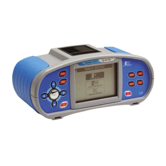
Page 5: Instrument Front Panel
MI 3017 Instaltest Instrument front panel 2. Instrument front panel Legend: 1..Switches the instrument power on or off. 2..Accesses help menus. 3..Adds new memory location/ Confirmation of name entered in edit mode. 4..Enters memory editing mode/ Deletes character on the left in edit mode. 5..Memory handling. -
Page 6: Auto Sequence
MI 3017 Instaltest Instrument front panel 3. Auto sequence Set function Set parameters and limits Select Auto sequence in Main menu. Select auto sequence step or parameter..Use cursors to select appropriate test Select test function or parameter value.. -
Page 7: Visual Inspection
MI 3017 Instaltest Measurements 4. Measurements 4.1. Visual inspection Set function Set parameters Select Single test in Main menu. Checklists. Item ..Use cursors to find and choose the VISUAL function. Use cursors to select appropriate checklist. Visual inspection procedure Disconnect tested installation from mains supply. -
Page 8: Insulation Resistance
MI 3017 Instaltest Measurements 4.1. Insulation resistance Set function Set parameters and limits Select Single test in Main menu. Sub-function TEST ..Use cursors to find and choose the Test configuration. INSULAT.RES. TEST ..function. Test voltage..Use cursors to sub-function (general, heating Minimum insulation resistance. -
Page 9: Resistance To Earth Connection And Equipotential Bonding
MI 3017 Instaltest Measurements 4.2. Resistance to earth connection and equipotential bonding Set function Set parameters and limits Select Single test in Main menu. Sub-function. TEST ... Use cursors to find and choose the Test current (200 mA, 7 Current .. - Page 10 MI 3017 Instaltest Measurements 4.3. Polarity Set function Set parameters and limits Select Single test in Main menu. Sub-function TEST ..Use cursors to find and choose the POLARITY function. For socket outlet (no supply): Use cursors to select sub-function (consumer mains selection of test configuration TEST ..
- Page 11 MI 3017 Instaltest Measurements 4.4. Correct circuit connections Set function Set parameters and limits Select Single test in Main menu. Sub-function. TEST ..Use cursors to find and choose the Correct CONN. function. For Lighting points, Socket outlets, Use cursors to select sub-function (lighting points, Equipment: socket outlets, equipment, conductors).
-
Page 12: Testing Rcds
MI 3017 Instaltest Measurements 4.5. Testing RCDs Set function Set parameters and limits Select Single test in Main menu. RCD sub-function test. TEST ..Use cursors to find and choose the Rated RCD residual current sensitivity I ..ΔN. function. RCD type [G, ], test current waveform type... - Page 13 MI 3017 Instaltest Measurements 4.6. Fault loop Set function Set parameters and limits Select Single test in Main menu. TEST Sub-function....Use cursors to find and Selection of breaking device (Fuse, RCD). Protection ..choose the function. Selection of fuse type (---, B, C, D, FUSE). FAULT LOOP Prot.
-
Page 14: Line Impedance And Prospective Short-Circuit Current
MI 3017 Instaltest Measurements 4.7. Line impedance and prospective short-circuit current Set function Set parameters and limits Select Single test in Main menu. Selection of fuse type [---, NV, Gg, B, C, K, D]. FUSE Type ..Use cursors to find and Rated current of selected fuse. -
Page 15: Voltage, Frequency And Phase Sequence
MI 3017 Instaltest Measurements 4.8. Voltage, frequency and phase sequence Set function Select Single test in Main menu. Use cursors to find and choose the function. VOLTAGE Circuits for voltage measurement Connection of universal test cable and optional adapter result 1.2.3 result 2.1.3 in three-phase system Connection of mains... -
Page 16: Resistance To Earth
MI 3017 Instaltest Measurements 4.9. Resistance to earth Set function Set parameters and limits Select Single test in Main menu. Maximum resistance Limit ..Use cursors to find and choose the function. [OFF, 1 Ω ÷ 19.9 kΩ]. EARTH Circuits for measuring resistance to earth MPEC >5d Resistance to earth measurement –... - Page 17 MI 3017 Instaltest Measurements 4.10. Locator Measurement procedure Select the function in MISC menu. LOCATOR Connect test cable to the instrument. Connect test leads to the energized tested object. Press the TEST key. Trace lines with receiver (in IND mode) or receiver plus its optional accessory. After tracing is finished press the TEST key again to stop generation of test signal.
-
Page 18: Maintenance
MI 3017 Instaltest Maintenance 5. Maintenance 5.1. Replacing fuses M 0.315 A / 250 V, 20x5 mm This fuse protects internal circuitry of low-value resistance function if test probes are connected to the mains supply voltage by mistake. F2, F3 F 4 A / 500 V, 32x6.3 mm General input protection fuses of test terminals L/L1 and N/L2. - Page 19 MI 3017 Instaltest Maintenance...
- Page 20 MI 3017 Instaltest Maintenance...
Need help?
Do you have a question about the Instaltest 3017 and is the answer not in the manual?
Questions and answers