
Subscribe to Our Youtube Channel
Related Manuals for Boulder 1110


Summary of Contents for Boulder 1110
- Page 1 1110 Preamplifier 2/1/2018 Boulder Amplifiers, Inc. Rev. 1.0 255 S. Taylor Ave. Louisville, CO 80027 (303) 449-8220 www.boulderamp.com P/N: 91054...
- Page 2 About About Boulder Amplifiers, Inc. Boulder was founded in 1984 and is the last high-performance audio manufacturer operating in North America to still perform all of its own design, engineering and manufacturing in-house. While this form of production may be more costly than outsourcing, the resulting quality control and reliability of the finished products are never compromised.
- Page 3 Please take a few minutes to read through this instruction manual prior to using your 1110. This will help you understand the many functions and capabilities of the preamplifier. It will also allow you to maximize the convenience and performance for which it was engineered.
- Page 4 • • • • • • • • • • • • • • • • • • • • • • • • • • • • • • • • • • • • • • • • • • • Placement and Installation of the 1110 Preamplifier •...
- Page 5 Table of Contents Front Panel Button Functions: Setup Screen 2-15 • • • • • • • • • • • • • • • • • • • • • • • • • Input Settings 2-15 •...
-
Page 6: Table Of Contents
• • • • • • • • • • • • • • • • • • • • • • • • • • • • • • • • • • • • • • • • • • • Boulder Net 4-18 •... - Page 7 • • • • • • • • • • • • • • • • • • • • • • • • • • • • • • • • • • • • • • • • • • • • • • • • 1110 Preamplifier Dimension Diagram •...
- Page 8 Getting Started Introduction The 1110 Preamplifier embodies years of development and is one of the most advanced preamplifiers available. Here are some of the features that set the 1110 apart from the competition: Analog features: • Proprietary, fully-balanced Boulder volume control •...
- Page 9 Preamplifier weighs 35 lbs. (16 kg). If possible, two people should unpack and place it into position. Be sure to save all packing materials! The 1110 is shipped in a foam wrap to protect the preamplifier’s fine finish. Try not to damage this wrap in the event that the unit must be transported elsewhere in the future.
- Page 10 Getting Started How to Clean the Casework If the 1110 must be cleaned, use only a soft, lint-free cloth moistened with plain water. Never use any type of chemical cleaner unless recommended by your dealer or the Boulder factory. Do not use bleach! Bleach will remove the anodized surface of the case- work.
- Page 11 This is necessary for the IR remote control to function properly. Because it is heavy, the 1110 system must be placed on a sturdy, stable surface. Do not place in an enclosed rack without ventilation. The 1110 must have at least 3 inches (8 cm) of airspace around the chassis for proper cooling and airflow.
- Page 12 Connect each source to one of the five inputs provided on the rear panel of the 1110. Later, you will be able to program each input with the source’s name (see HTML Programming: Setup on page 4-11), so you may want to...
- Page 13 It converts a balanced input into a RCA phono input at the rear of the 1110. Like the above cable, the negative input of the 1110 is connected to the ground of the RCA phono. However, this negative side will then share the shield wire with the chassis ground and will not have the best hum rejection.
- Page 14 The Ethernet connections are for Internet access in order to program input names or download software updates for the 1110. One of the Ethernet jacks should be connected to a network with an active Internet feed. Because they are switched, it does not matter which jack is used.
- Page 15 (input) cables. With the low output impedance of the 1110, distances of more than 50 me- ters between preamplifier and power amplifier are practical.
- Page 16 Polarity Please note that the 1110 Preamplifier conforms to the standard of Pin 2 as high or “hot” for all analog balanced inputs and outputs. Because input and output polarities are handled through the Setup menu and the remote...
- Page 17 Use either Ethernet connector on the rear panel of the 1110; it does not matter which one you use. It is possible to confirm that the 1110 is connected to a network. To do so, press the Option button on the front panel, then the Setup button, then press the System Info button.
- Page 18 Connect the AC power cord to the Master AC Power Switch connection on the rear panel of the 1110 as shown and plug the other end into AC mains. AC Mains 1-11...
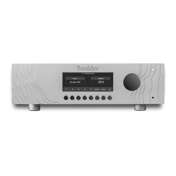
- Page 20 Operation Front Panel Controls and Screen Modes The 1110 features a full-color LCD display and a large Control Knob on the right-hand side of the front panel. The Control Knob will adjust different functions of the 1110, depending on the mode that the preamplifier is in.
- Page 21 Operation...
- Page 22 When the display is showing the Home Screen, the Control Knob will con- trol the Volume of the 1110. At other times, when the 1110 is in the Option or Setup modes, the Control Knob will adjust programmable features of the 1110’s operation.
- Page 23 Operation...
- Page 24 Front Panel Button Functions: Home Screen Inputs 1 – 5 The 1110 has five inputs. Each of these inputs can be directly selected by pressing the button that corresponds with the input you wish to select. To select an input, press one of the push buttons labeled Input 1 through Input 5 on the front panel.
- Page 25 Operation Input 1 Input 2 Input 3 Input 4 Input 5...
- Page 26 Mute The volume level of the 1110’s Main Outputs can be temporarily reduced for instances such as a short conversation or telephone call. To temporarily attenuate the volume, press the Mute button. Pressing the Mute button again will return the output level to the previous volume setting.
- Page 27 Operation...
- Page 28 Standby mode, it is only necessary to place the unit in Standby when not in use. You do not need to turn the 1110 off via the Master AC Switch on the rear panel of the preamplifier. The 1110 was designed for years of opera- tion in this manner and no damage to the unit will occur.
- Page 29 Operation Rotating the control to the left, or counter-clockwise, will cause an indi- cation such as “R -2.0 dB” in the Balance display. This will attenuate the right channel -2.0 dB below the left channel, regardless of volume setting, making the left channel louder. The range of balance offset is limited to -20.0 dB.
- Page 30 Operation Display The brightness of the display can be adjusted as well as turning the display completely off. The Display setting determines the brightness of the display, from 0% (off) to 100% (full brightness). To change the brightness level, press the Display button. The display will show two boxes, one on the left reading Display Brightness and the other on the right side showing the level of display brightness.
- Page 31 0 to 360 degrees. The term “polari- ty” is used to indicate 180° phase change, or inversion, as available in the 1110 Preamplifier. The polarity of all active Main Outputs can be changed by pressing the Polarity Absolute button on the front panel while in Option mode.
- Page 32 0 to 360 degrees. The term “polarity” is used to indicate 180° phase change, or inversion, as available in the 1110 Preamplifier. The polarity of only the right channel of the outputs can be changed by...
- Page 33 Pressing the Setup button will change the display from the Home Screen to the Setup Screen. When the Setup Screen is shown, the function of certain buttons will change and the 1110’s operation can be changed to suit your preferences. 2-14...
- Page 34 Operation Front Panel Button Functions: Setup Screen The functions of all buttons on the front panel except for Mute will change when the Setup button is pressed. If the Setup button is pressed but no activity takes place, the display will automatically revert to the Home Screen after 30 seconds.
- Page 35 Operation Input Trim When Input Settings button is pressed, two boxes below will appear on the front panel display. On the left side of the display will be a box showing the Input available for adjustment, and on the right side of the display will be a box that indicates the level of Trim adjustment (output reduction) in Input Trim allows you to reduce the volume of a selected input relative to all others so that they can be matched to the same level.
- Page 36 0 to 360 degrees. The term “polari- ty” is used to indicate 180° phase change, or inversion, as available in the 1110 Preamplifier. If you are unsure of the output polarity of your source components, please see their associated instruction manuals.
- Page 37 After the desired balance is reached, or if no change is desired, press any button on the front panel. The display will now change to the Input Polarity screen. Pressing the Input Settings button a fourth time will cause the 1110 to return to the Setup Screen. 2-18...
- Page 38 WARNING: Theater Mode should be used with extreme caution, as there is no way to control the volume of the 1110 while in Theater Mode! If it is programmed for an input that does not have externally controlled volume, damage to speakers or other components may occur! WARNING: If the input is programmed for “THEATER MODE,”...
- Page 39 Operation 2-20...
- Page 40 “-100 to 0” to “0 to 100” or anywhere in between. This feature allows you to set the volume control of the 1110 to the scale of your choice. For example, one possibility would be to set the scale to “-80 TO 20” indi- cating the actual gain in decibels (dB) of the Boulder 1110 Preamplifier.
- Page 41 “Volume Resolution” will appear on the left side of the display along with a selection choice on the right. Volume Resolution will deter- mine the step resolution of the 1110 Preamplifier’s volume control. Steps of 0.5 dB (200 steps) or 1.0 dB (100 steps) can be chosen.
- Page 42 The default output level setting upon power-up can be programmed to prevent loud settings from previous listening sessions. For example, setting the Volume Default level at -60.0 dB will cause the 1110 to always set the volume at -60.0 dB when coming out of Standby.
- Page 43 Operation Volume Max Once you have chosen a Volume Default setting, press any button on the front panel. “Volume Max” will appear on the left side of the display along with a selection choice on the right. The maximum allowable volume setting can be also programmed to prevent children or other users from turning the system up too loud.
- Page 44 Operation Mute Level It is possible to Mute the 1110’s outputs so that they are reduced by a pre- programmed level. The Mute feature allows for temporary volume reduction without losing the original setting. The level of Mute mode attenuation is indicated in dB (decibels).
- Page 45 It is permanent and cannot be changed by the user. IP Address: If the 1110 is attached to an active network, the IP address of the unit will be indicated here. This is useful when accessing the HTML page for programming.
- Page 46 If you encounter problems where the IR remote control interferes with the operation of other electronic devices in your home, you will need to change the remote address for the 1110 and for the handheld IR remote control. To change the Remote Address, press the Remote Address button on the front panel while on the System Info screen in Setup mode.
- Page 47 Operation 2-28...
- Page 48 Restore Factory Defaults button. To restore the 1110 to the original factory default settings, press the Setup button, followed by the Restore Factory Defaults button. The front panel display will show “Restore Factory Defaults?” To restore the 1110 to the original factory settings, press the Restore button.
- Page 49 Operation Return to Home Pressing the Return to Home button will change the display to the Home Screen mode and return all buttons to their Home Screen functions. 2-30...
- Page 50 Remote Control Remote Control The 1110’s handheld remote control can be used to control all of the pre- amplifier’s functions. Most of the buttons on the remote control will have the same function as the buttons on the front panel of the 1110.
- Page 51 To replace the batteries in the remote control, use a Phillips #1 screwdriver to remove the four screws that secure the back panel of the remote. This type of screwdriver is included in the 1110 Accessory Kit. The battery type is a CR2032 “coin” style battery. Insert the tip of a 1/8”...
- Page 52 2. Press the Remote Address button. 3. Rotate the Control Knob until the Remote ID number that matches the setting for the remote control is shown in the 1110 display. 4. Press any button on the front panel to exit the Setup menu.
- Page 53 Remote Control Switch 3 In ON Position 0 1 2 3 4 5...
- Page 54 Standby mode, it is only necessary to place the unit in Standby when not in use. You do not need to turn the 1110 off via the Master AC Switch on the rear panel of the preamplifier. The 1110 was designed for years of opera- tion in this manner, so that no damage to the unit will occur.
- Page 55 Remote Control Volume Up and Volume Down To increase the volume of the 1110, press the button next to the UP arrow ). Holding the button will continue to raise the volume quickly until the button is released. To reduce the volume, press the button next to the DOWN arrow ( Holding the button will continue to lower the volume quickly until the button is released.
- Page 56 “phase” indicates any angle between two channels, from 0 to 360 degrees. The term “polarity” is used to indicate 180° phase change, or inversion, as available in the 1110 Preamplifier. Pressing the POL button on the remote control will reverse or invert the polarity of the Main Outputs.
- Page 57 Remote Control Display Pressing the DISP button will adjust the brightness of the display as well as turn the display completely off. The Display setting determines the brightness of the display in 20 steps, from 0% (off) to 100% (full brightness). To change the brightness level, press the DISP button.
- Page 58 If a firmware update is available, you will also see the following: Update Available: IP Address: If the 1110 is attached to an active network, the IP address of the unit will be indicated here. This is where you will find the information to access the HTML page for programming.
- Page 59 Page Tabs The HTML screen is divided into four tabbed pages: Main Page, Options, Setup and Boulder Net. The tabs for these pages can be found in the upper left-hand corner of the HTML screen. Clicking on each tab will...
-
Page 60: Master Volume
Master Volume The Master Volume Slider adjusts the volume control and attenuation of the 1110. When adjusted, the Master Volume Slider will control the level of both outputs simultaneously and has a range from INF (infinite attenuation) to 0.0 dB (+20.0 dB of gain and maximum output). The volume control setting will appear under the left side of the Master Volume Slider. -
Page 61: Settings
There is one checkbox on the Main Page: Mute. Mute It is possible to Mute the outputs so that the 1110’s outputs are reduced by a preprogrammed level. The Mute feature allows for temporary volume reduction without losing the original setting. The level of Mute attenuation is indicated in dB (decibels). -
Page 62: Balance
Programming Balance The Balance Slider adjusts the left-to-right level balance. When the output from both channels is equal “Center” will show in the Balance portion of the front panel display. To shift the balance to the right, click on the Balance Slider and move it to the right. -
Page 63: Input Trim
Toggle Standby The 1110 can be toggled in and out of Standby mode. To place the 1110 in Standby, click on the button marked Standby. To bring the 1110 out of Standby mode, click on the button marked Stand- by again. -
Page 64: Upload Logs
Programming Upload Logs The 1110 keeps a running log of errors and system faults. At times it may be useful to send these logs to the Boulder factory to help eliminate soft- ware bugs or improve development. To do so, the 1110 must be connected to a network with an active Internet feed. -
Page 65: Options Tab
Programming Options Tab Mute It is possible to Mute the outputs so that the 1110’s outputs are reduced to infinite attenuation. To mute the outputs, click on and mark the checkbox marked Mute. To unmute the outputs, click on and unmark the checkbox marked Mute. -
Page 66: Polarities
180° phase change, or inversion, as available in the 1110 Preamplifier. The outputs of the 1110 default to Pin 2 “High” or hot. The Polarities checkboxes will allow you to adjust the polarity of the outputs. -
Page 67: Polarity Right Channel
0 to 360 degrees. The term “polari- ty” is used to indicate 180° phase change, or inversion, as available in the 1110 Preamplifier. It is possible to invert the polarity of only the right channel of the Main Out- puts. -
Page 68: Setup Tab
Click on the Name text box and type the new input name you would like within the box, then click on the button marked Set Name. The new name will now appear on the 1110’s front panel display. It is possible to rename all of the 1110’s inputs this way. -
Page 69: Balance
Programming Balance The Balance Slider adjusts the left-to-right level balance in 0.5 dB steps. When the output from both channels is equal “Center” will show below the left side of the Balance Slider. To shift the balance to the right, click on the Balance Slider and move it to the right. -
Page 70: Polarity
Programming Polarity Each input of the 1110 defaults to Pin 2 “High” or hot. The Polarity check- box will allow you to invert the polarity of an input to compensate for a source with inverted output. To invert the polarity of a specific input, click on the Polarity checkbox. -
Page 71: Restore Default Input Names
Room The 1110 may be used as a part of a larger, whole-home audio system in an Open Home system and can be named to make identification of the system being used easier. -
Page 72: Volume Resolution
For example, setting the Volume Default level of -60.0 dB will cause the 1110 to always set the volume at -60.0 dB when coming out of Standby. To enter the Volume Default, click on the Volume Default slider and move the slider until the desired Default Volume setting is indicated under the left side of the Volume Default slider. -
Page 73: Max Volume
Programming Max Volume The maximum allowable volume setting can be programmed to prevent children or other users from turning the system up too loud. Settings in 1.0 dB steps from -100.0 dB to 0.0 dB or anywhere in between can be en- tered. -
Page 74: Mute Level
Programming Mute Level The level of attenuation for the Mute mode can be programmed. Settings in 1.0 dB steps from -100 dB to 0.0 dB or anywhere in between can be entered. For example, when the Mute Level is set to -15.0 dB, the volume will drop -15.0 dB from its original setting. -
Page 75: Settings
It is possible to restore all programming to the original, factory default set- tings by pressing the Reset Factory Defaults button. To restore the 1110 to the original factory default settings, click on the blue Restore Factory Defaults button. The 1110 will immediately restore the original factory settings. - Page 76 Appendix Technical Specifications Balanced Inputs 5 x 3-pin XLR Balanced Outputs 2 x 3-pin XLR AUX Balanced Outputs 1 x 3-pin XLR Maximum Input Level 6.0 Vrms Maximum Output Level 14.0 Vrms THD+N, 2V Output, from 20 Hz to 20 kHz 0.0015% (-96.5 dB) Maximum Voltage Gain 20 dB...
- Page 77 Appendix Weights and Dimensions 1110 Preamplifier Chassis: 18.0” W x 15.3” D x 5.7” H (36 lbs.) 45.7 cm W x 38.9 cm D x 14.5 cm H (16.3 kg) Shipping: 24.0” W x 23.0” D x 16.0” H (49 lbs.) 61.0 cm W x 58.5 cm D x 40.5 cm H...
- Page 78 Appendix 1110 Preamplifier Dimensions (Inches) 15.307 15.115 15.307 15.115 1110 PREAMPLIFIER 15.307 DIMENSIONS 18.000 5.730 18.000 1.469 .977 13.000 2.500 5.730 1.469 .977 13.000 2.500 5.730 1.469 .977 9.500 3.120...
- Page 79 Appendix Troubleshooting SYMPTOM CAUSE REMEDY No power Master AC Power Switch on rear Turn on Master AC Power Switch indication panel is not ON Preamplifier is not plugged in Connect power cord to AC mains outlet Preamplifier fuse is blown Replace preamplifier fuse Home circuit breaker is tripped Reset home circuit breaker...
- Page 80 Appendix Notes:...
- Page 81 Appendix Notes:...
- Page 82 Appendix Notes:...
- Page 83 Appendix Notes:...
Need help?
Do you have a question about the 1110 and is the answer not in the manual?
Questions and answers