Table of Contents
Advertisement
Quick Links
Advertisement
Table of Contents

Related Manuals for Boulder 860


Summary of Contents for Boulder 860
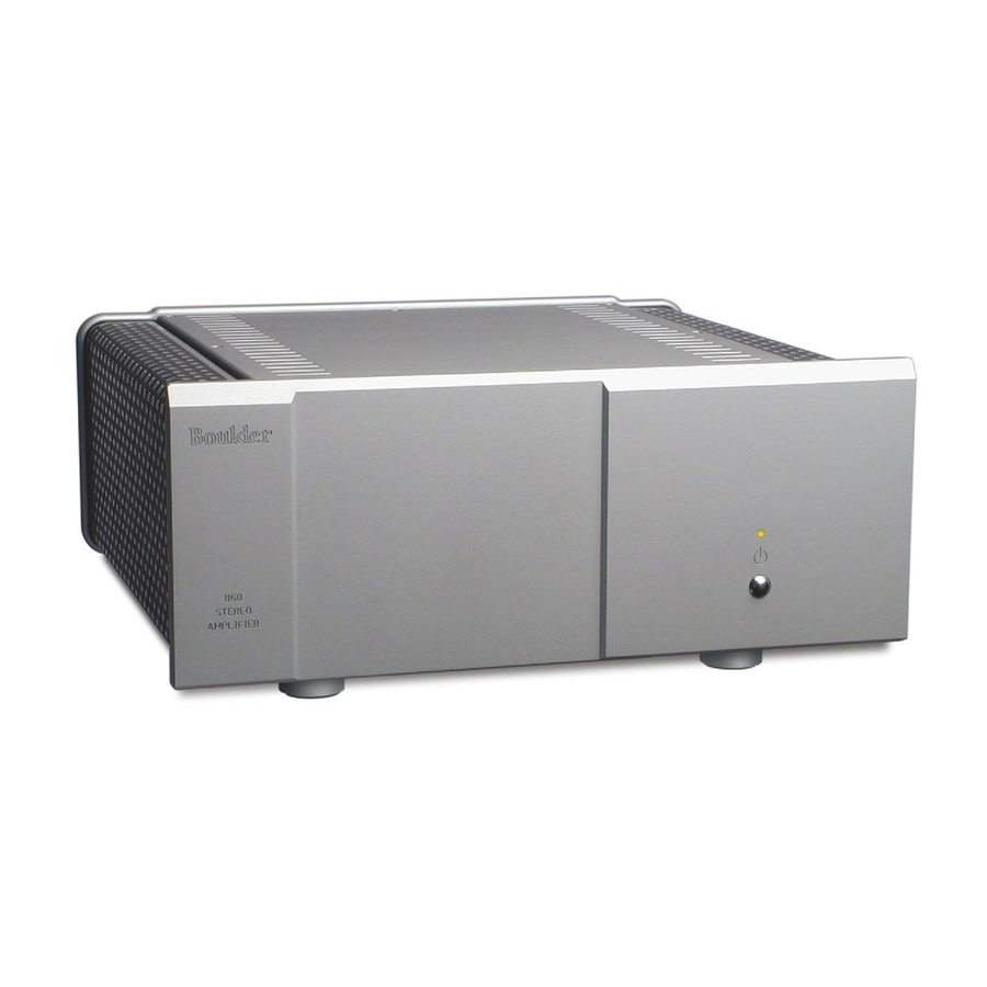
- Page 2 Boulder 860 150 Watt Stereo Power Amplifier Instruction Manual 6/13/07 Boulder Amplifiers, Inc. 3235 Prairie Ave. Boulder, CO 80301 www.boulderamp.com BOULDER REMOTE GETTING APPENDIX LINK CONTROL OPERATION STARTED...
- Page 3 B o u l d e r 8 6 0 S t e r e o P o w e r A m p l i f i e r R e a r P a n e l BOULDER REMOTE GETTING APPENDIX...
-
Page 4: Table Of Contents
Placement of the 860 Stereo Power Amplifier........ - Page 5 APPENDIX Specifications ............. . 5-1 Troubleshooting .
-
Page 6: Getting Started
G ETTI NG START ED PLACEMENT OF THE 860 STEREO POWER AMPLIFIER Your Boulder 860 Stereo Power Amplifier is designed to reduce interference from external magnetic and radio fields (RF). While placement is not critical, known magnetic fields should be avoided. -
Page 7: Connecting To The Mains Outlet
Exact voltage and frequency compatibility is stated in the specifications section. Once the 860 Stereo Power Amplifier is connected to a live mains outlet and the mains power switch turned on, the front panel indicator will be illuminated. The indicator will be of varying color, showing that the supervising microprocessor is powered up and ready. -
Page 8: Connecting A Balanced Source
CONNECTING A BALANCED SOURCE To fully realize the sonic potential of your 860 Stereo Power Amplifier, use balanced connections whenever possible. Balanced cables reduce interference from magnetic and RF sources to an absolute minimum. Connect your preamplifier or source outputs to the inputs provided. -
Page 9: Connecting An Unbalanced Source
RCA phono type connector on the source end and a three- pin XLR connector to go to the input of the 860 Stereo Power Amplifier. The negative input (Pin 3) should be wired to ground only at the RCA phono connector. -
Page 10: Polarity
Please note that the 860 Stereo Power Amplifier conforms to the standard of Pin 2 as the high or ”hot” for the balanced inputs. The polarity of the 860 Stereo Power Amplifier is such that a positive- going transition at Pin 2 will produce a positive-going transition at the “+”... -
Page 11: Operation
POWERING UP With all your connections made, you are ready to listen to your Boulder 860 Stereo Power Amplifier. To turn the amplifier on, press the STANDBY button on the front panel. The amplifier will perform a warm up cycle and the indicator will alternate between red and amber for 45 seconds. -
Page 12: Clip Detection
CLIP DETECTION Clipping of the waveform results when any amplifier is driven at too high a level. A clip detection circuit is included in the 860 Stereo Power Amplifier. The indicator will indicate clipping by momentarily turning from amber to red. Both voltage and current modes of clipping will be detected, although generally it is only voltage clipping which occurs. -
Page 13: Shorted Output Detection
If this happens, more ventilation should be provided for the amplifiers. MAINTENANCE No routine maintenance is required for the Boulder 860 Stereo Power Amplifier. However, to keep operating temperatures at a minimum, do not block the heat sinks, and remove any dust buildup that may occur. -
Page 14: Remote Control Operation
With a trigger connection, the 860 will be on when the voltage is +5 to +12 volts, and off when the voltage is 0 volts. The tip of the mini phone plug should be positive with respect to the sleeve. -
Page 15: Boulderlink
Turn off all products to be linked before connecting any Boulderlink cables and setting the Boulderlink ID and Master/Slave switches. Two connectors are provided on the back of the 860 and other Boulderlink enabled products. Boulderlink cables in various lengths are available as an accessory from your Boulder dealer. -
Page 16: Setting Boulderlink Switches
Every component is required to have a unique Boulderlink ID number. Each Boulder 860 Stereo Power Amplifier has a thumbwheel switch on the rear panel. Start by setting the switch on the first amplifier to 0 or 1 and then increment up from there without any duplication. Use of the lowest numbers will speed up turn-on as each amplifier is allowed about three seconds before the next. -
Page 17: Power Up Via Boulderlink
POWER UP VIA BOULDERLINK With each component connected together by a Boulderlink cable, and individually connected to the mains, pressing the master’s STANDBY pushbutton will initiate the turn on sequence of all components. The first time a master is powered up, it will search for any “slave” units connected to it. -
Page 18: Boulderlink Messages
BOULDERLINK MESSAGES Each component in the system can send a message to the preamplifier which is then shown on its display. This is particularly helpful in confirming the operating status of each power amplifier in a multiple amplifier system. Typical messages on an 810 Preamplifier, 1010 Preamplifier or 1012 DAC Preamplifier are as follows. - Page 19 BO UL DE R 8 60 S T E RE O P O W ER AMPLI FIER SPECI FI CATI ONS THD at Continuous Power, 20 to 2KHz THD at Continuous Power, at 20KHz Continuous Power, 8 Ω Continuous Power, 4 Ω Peak Power, 8 Ω...
-
Page 20: Troubleshooting
SYMPTOM No power indication Red power indication Amber power indication, but sound not heard from one channel APPENDIX TROUBLESHOOTING CAUSE Power switch is not on Power amplifier is not plugged in Home circuit breaker is tripped Fuse on rear panel blown Low line voltage Power supply breaker tripped Defective amplifier... - Page 21 NOTES APPENDIX...
Need help?
Do you have a question about the 860 and is the answer not in the manual?
Questions and answers