Table of Contents
Advertisement
Advertisement
Table of Contents

Related Manuals for Boulder Integrated Amplifier 865


Summary of Contents for Boulder Integrated Amplifier 865
-
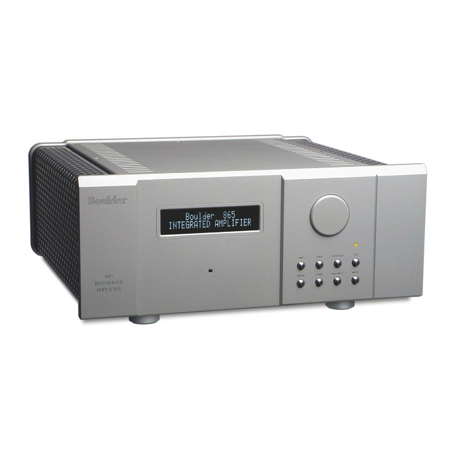
Page 2: Integrated Amplifier
Boulder 865 Integrated Amplifier Instruction Manual 10/1/07 Boulder Amplifiers, Inc. 3235 Prairie Ave. Boulder, CO 80301 www.boulderamp.com BOULDER REMOTE GETTING APPENDIX RECORDING LINK PROGRAMMING CONTROL OPERATION STARTED... - Page 3 B o u l d e r 8 6 5 I n t e g r a t e d A m p l i f i e r R e a r P a n e l BOULDER REMOTE GETTING APPENDIX RECORDING...
-
Page 4: Table Of Contents
Setting the Boulderlink Switch ........ - Page 5 REMOTE CONTROL Batteries ..............3-1 Source Selection .
- Page 6 BOULDERLINK Connecting the Boulderlink ..........5-1 Connecting 800 Series to 1000 or 2000 Series with Boulderlink.
-
Page 7: Getting Started
See the troubleshooting section on page 7-3. For the 865 to work properly, the Boulderlink MASTER/SLAVE switch should be set to MASTER in most instances. See page 1-9. A thorough reading of this manual prior to use and set up will greatly enhance your enjoyment of the 865 Integrated Amplifier. -
Page 8: Placement Of The 865 Integrated Amplifier
PLACEMENT OF THE 865 INTEGRATED AMPLIFIER Your Boulder 865 Integrated Amplifier is designed to reduce the effects that external magnetic and radio fields (RF) have on its internal circuitry. While placement is not critical, known magnetic fields should be avoided. Line of sight from the listening position is necessary for the remote control to function properly. -
Page 9: Connecting To The Mains Outlet
CONTACT YOUR DEALER IMMEDIATELY. Once the 865 is connected to a live mains outlet and the mains power switch is turned on, the front panel indicator will be illuminated. The indicator will be of varying color, showing that the supervising microprocessor is powered up and ready. -
Page 10: Polarity
POLARITY Please note that the 865 Integrated Amplifier conforms to the standard of Pin 2 as the positive or ”hot” pin for all analog balanced inputs and outputs. CONNECTING A BALANCED ANALOG SOURCE To realize the greatest sonic potential of your 865 Integrated Amplifier, use balanced connections whenever possible. -
Page 11: Connecting An Unbalanced Source
CONNECTING AN UNBALANCED SOURCE Although the inputs are all of the 3-pin XLR type, an unbalanced source is easily accommodated by using a special cable. This cable has an RCA phono type connector on the source end and a 3-pin connector (for an input) at the 865 Integrated Amplifier. -
Page 12: Connecting The Auxiliary Outputs
CONNECTING THE AUXILIARY OUTPUTS The auxiliary output level of the 865 Integrated Amplifier can be set to either a fixed mode suitable for use with a recording device or music distribution system; or a variable mode for use with a subwoofer or secondary amplifier. -
Page 13: Connecting The Auxiliary Outputs To Acomponent With Unbalanced Inputs
CONNECTING THE AUXILIARY OUTPUTS TO A COMPONENT WITH UNBALANCED INPUTS The 865 Integrated Amplifier’s balanced outputs can drive unbalanced inputs with a cable having an XLR connector at the source (865) end and an RCA connector at the load end. A special cable required to make this connection connects Pin 1 to the shield and Pin 2 to the RCA center conductor. -
Page 14: Polarity
POLARITY Please note that the 865 Integrated Amplifier conforms to the standard of Pin 2 as the high or ”hot” for the balanced inputs. The polarity of the 865 is such that a positive-going transition at Pin 2 will produce a positive-going transition at the ”+” loudspeaker terminal. -
Page 15: Setting The Boulderlink Switch
SETTING THE BOULDERLINK SWITCH The normal setting of the MASTER / SLAVE switch is MASTER. When using the 865 with only power amplifiers, the Boulderlink MASTER / SLAVE switch should be set to MASTER. For more information on Boulderlink, see the Boulderlink section 5-1 as indicated by the finger tab below. -
Page 16: Operation
During the power up sequence, the displays at left will be briefly shown. The front panel STANDBY button should be used for everyday turn on and off. This switch mutes the audio, turns off all sections except the microprocessor, and puts the 865 in standby mode. OPERATION... -
Page 17: Input Selections
INPUT SELECTIONS To select an input, press one of the pushbuttons labeled ONE, TWO, THREE or FOUR. The respective input will be shown in the display and that signal will be routed to both the loudspeaker and auxiliary outputs. For example, if input ONE is chosen, “1. INPUT ONE” will show in the display. -
Page 18: Volume
VOLUME Because the precise feel of the Boulder 865’s volume control may be different than you are used to, we recommend starting the source device so that an audio signal is fed to the 865 before increasing the volume. The display will show “VOLUME INFINITE” to indicate maximum attenuation or no sound. -
Page 19: Balance
BALANCE To change the level balance, press the BALANCE pushbutton. “BALANCE CENTERED” will show in the display. Now, rotating the control will change the balance instead of the volume for as long as “BALANCE...” is displayed. Turning the control counterclockwise (left) will cause an indication such as “BALANCE R -2.0dB <... -
Page 20: Mute
After several seconds of not changing the balance, the display will return to the “VOLUME...” indication. You may also return to controlling volume by again pressing the BALANCE pushbutton. The balance resolution is the same as for the volume control, 0.5 dB steps. WARNING: If the input is programmed to be in “THEATER MODE,”... -
Page 21: Display
DISPLAY The display brightness may be set to any of four brightness levels. To change the brightness level, press the DISPLAY pushbutton. “DISPLAY 100%” will show in the display. Rotate the center control until the desired brightness is obtained such as “DISPLAY 50%.” The number in the display is the relative brightness. -
Page 22: Remote Control
REM OTE CONT ROL BATTERIES A standard small flat-blade screwdriver is required to install the three AAA batteries. To install batteries in the remote control, it is necessary to separate the two sections. WARNING: When opened, the pushbutton balls will be loose and care must be taken to properly retain them. -
Page 23: Source Selection
SOURCE SELECTION To select an input (source) press the button on the left side of the remote control whose number corresponds to the input you wish to listen to, and it will show in the display. You will now be listening to your desired input. -
Page 24: Programming
PROGRAMMI NG While it is not necessary to ever use any programming functions, you will find they maximize the enjoyment of your Boulder 865 Integrated Amplifier. Each input has several programmable features associated with it. These include assigning an alphanumeric name of your choosing, setting an individual start volume and balance, and setting Theater Mode. - Page 25 If you chose to assign a name, then “1 INPUT ONE” will be shown in the bottom display row with a blinking cursor before the name’s first character. Rotate the control until the desired character appears. Press the same input source number to accept the displayed character and go to the next character.
-
Page 26: Input Level Calibration
INPUT LEVEL CALIBRATION Pressing the same input source number will make “INPUT LEVEL 0.0dB” show in the bottom display row. Rotating the volume control will change the display and the loudspeaker levels simultaneously. This allows calibration of each input with test tones if desired. For example, setting the display to “-6.0dB”... -
Page 27: Input Balance Calibration
INPUT BALANCE CALIBRATION Pressing the same input source number will make “INPUT BAL CENTERED” show in the bottom display row. Rotating the volume control will simultaneously change the display and the loudspeaker balance so that the action can be monitored or measured. For example, setting the display to “R -9.0dB”... -
Page 28: Theater Mode
THEATER MODE When the 865 Integrated Amplifier is used in a surround sound or home theater system, it is normally desired to bypass the volume control, thus letting the surround processor control the volume. WARNING: Setting an input to THEATER MODE forces the volume to unity gain. -
Page 29: Programming By The Display Button
PROGRAMMING BY THE DISPLAY BUTTON Several special features are programmed by pressing and holding the DISPLAY pushbutton until the display changes, indicating you are in a programming mode. If no action is taken for some time, then the 865 reverts back to normal operation. The sequence is as follows. AUXILIARY OUTPUTS MODE A separate pair of balanced outputs are provided for connection to other components. -
Page 30: Boulderlink Id
BOULDERLINK ID Pressing the DISPLAY pushbutton again will make “PROGRAM BOULDER LINK, BOULDER LINK ID 0” show in the display. Rotating the volume control changes the ID number. For more information consult the Boulderlink section. Unless you are using two or more 865 Integrated Amplifiers together, this setting should be left at “0.”... -
Page 31: Reset To Factory Defaults
RESET TO FACTORY DEFAULTS Should you wish to have all settings reset to original factory defaults, you may execute a master reset. Normally, this function is not used. Press and hold the STANDBY pushbutton. “RESET ALL PARAMETERS, INPUT 1=Y, INPUT 2=N” will show in the display. To leave all settings as they currently are, press the TWO pushbutton. -
Page 32: Boulderlink
BOULDERLINK "DAISY CHAIN" BOULDER BOULDER BOULDER PRE- POWER POWER AMPLIFIER AMPLIFIER AMPLIFIER MASTER SLAVE SLAVE BOULDERLI NK Boulderlink is a means of interconnecting most Boulder products TO ALL OTHER so that their microprocessors can talk to each other and pass important SLAVE information. -
Page 33: Connecting 800 Series To 1000 Or 2000 Series With Boulderlink
CONNECTING 800 SERIES TO 1000 OR 2000 SERIES WITH BOULDERLINK If you are using the 865 Integrated Amplifier with certain other Boulder products, a Boulder Link Adapter Box (BLAB) might be required to make the connection. Although the connectors are mechanically different between the series, they are electrically the same, thus allowing the various series to be mixed. -
Page 34: Setting Boulderlink Switches
Each Boulder power amplifier has a thumbwheel switch on the rear panel. Start by setting the first switch to 0 or 1 and then going up from there without any duplication. Use of the lowest numbers will speed up turn on as each amplifier is allowed about 3 seconds before the next. -
Page 35: Power Up Via Boulderlink
POWER UP VIA BOULDERLINK With each component connected together with a Boulderlink cable, and individually connected to the AC mains, pressing the 865’s STANDBY pushbutton will initiate the turn-on sequence of all components. The first time a “MASTER” 865 is powered up, it will search for any “slave”... - Page 36 If there is no component set to “MASTER,” the 865 will display “THERE IS NO MASTER!” In this case, the 865’s MASTER/SLAVE switch should be set to MASTER. It may take up to 30 seconds for the 865 to recognize the switch change.
-
Page 37: Boulderlink Messages
BOULDERLINK MESSAGES Each component in the system can send a message to the 865 which is then shown on its display. This is particularly helpful in confirming the operating status of each power amplifier in a multiple amplifier system. “AMPLIFIER 1 ERROR” means that an internal power supply has failed and the amplifier has turned itself off to protect the speakers from damage. - Page 38 “UNIT 1 IS OFFLINE” means that the slave is no longer responding via Boulderlink. Its Boulderlink cable may have become disconnected, or the AC mains power has been disconnected. “UNIT 1 IS ONLINE” means that the slave is now responding via Boulderlink in a normal manner and has been recognized by the master.
-
Page 39: Recording
RECORDING RECORDING The Auxiliary outputs may be used for making recordings or supplying a fixed level output to other system components. CONNECTING A RECORDING DEVICE A recording device may be connected to the 865 Integrated Amplifier. You may use balanced or unbalanced connections as previously described in the sections on connecting Auxiliary outputs. -
Page 40: Appendix
APPENDIX... -
Page 41: Specifications
BO UL DE R 8 65 IN T EG R ATE D AM PLIFI ER SPECI FI CAT I ONS Balanced Line Inputs Auxiliary Balanced Outputs Loudspeaker Output Connectors Continuous Power, 8, 4 Ohms Peak Power, 4 Ohms THD at Continuous Power Signal to Noise Ratio (re: 150W/8 Ohms) Frequency Response, 20 to 20 kHz Frequency Response, -3 dB... -
Page 42: Troubleshooting
Amber power indication, but sound not heard from one channel APPENDIX TROUBLESHOOTING CAUSE Amplifier is not plugged in AC mains power switch in OFF position Fuse open or missing Low line voltage Power supply breaker open Amplifier is defective No signal from source... -
Page 43: Notes
NOTES APPENDIX...
Need help?
Do you have a question about the Integrated Amplifier 865 and is the answer not in the manual?
Questions and answers