Table of Contents
Advertisement
Advertisement
Table of Contents

Related Manuals for VWR Micro Star 12


Summary of Contents for VWR Micro Star 12
-
Page 5: Table Of Contents
Notes and Warnings ........................Safety Information ......................... Package Contents ......................... Installation............................Intended Use ..........................Overview............................Operation............................Maintenance and Care ........................Trouble Shooting ........................... Accessories ........................... Technical service .......................... Warranty ............................Equipment disposal ........................Appendix ............................Local VWR offices in Europe and Asia Pacific................ -
Page 6: Warnings
NEVER use a power source other than that designated for the instrument. NEVER operate the instrument, if it has not been installed or repaired properly. Repairs must be performed only by qualified personnel authorized by VWR NEVER use unapproved rotors and associated components. Contact the manufacturer prior to such use to prevent possible damage to the instrument. - Page 7 NOTE When it is required to handle the Risk Group II materials that are known to be toxic, radioactive materials or pathogenic micro-organisms, as identified in the World Health Organization (WHO): “Laboratory Biosafety Manual,” the guidelines recommended by WHO should be followed to ensure the safety. (http://www.who.int/csr/resources/publications/biosafety/Labbiosafety.pdf) ...
-
Page 8: Package Contents
Package Contents Main Body, 1 unit Rotor: Autoclavable fixed angle rotor with 12 tube holes for 1.5 / 2.0 ml tubes, 1 unit Rotor Lid: Autoclavable biosafety rotor lid, 1 unit Adapter: Adapter for 0.2 ml PCR tubes, 12 units Power Supply: AC Power Cable (3m), 1 unit L-type rotor wrench, 5 mm, 1 unit Operation Manual, 1 unit... -
Page 9: Intended Use
Its user-friendly control features and compact, space-saving design delivers maximum solid performance for your daily centrifugation needs. VWR Micro Star 12 is supplied with an easily interchangeable rotor to accommodate micro-tubes and (with optional rotor) PCR strips. - Page 10 [Schematic diagram of mini’s air flow design] The patented, unique internal design circulates an efficient airflow inside the instrument, reduces spinning frictions, whilst minimizing both the motor temperature and the noise levels. SPECIFICATIONS Angle Rotor PCR Rotor Maximum RPM 13,500 rpm 6,000 rpm Maximum RCF 12,300 x g...
-
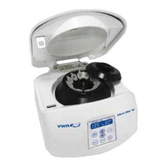
Page 11: Overview
Overview PHYSICAL DESCRIPTION Door Door Lock Ventilating Hole & Center Win Rotor Rotor Lid Control Panel Power Switch Power Socket Emergency Door Open Hole FRONT CONTROL PANEL DESCRIPTION 1. Display LCD control panel: Displays set values and actual operating conditions ... -
Page 12: Operation
2. Speed/force Setting Button: Press to set speed/force value and to switch between RPM and RCF. 3. Door Button: Press to open door. 4. Time Setting Button: Press to set run time between 1 min to 30 min. 5. Pulse Button: Press to use for quick separation. 6. -
Page 13: Maintenance And Care
Speed/Force: Press the “RPM/RCF” button and press the arrow buttons (▲, ▼) to select or change speed in increments of 100 RPM from 1,200-13,500 RPM. NOTE Press the “RPM/RCF” button once again to enter or change the force in RCF or convert speed in RPM to RCF. - Page 14 All parts MUST be shipped along with “Return Authorization Document” (RAN) and “Certificate of Decontamination.” Please contact VWR Service to obtain the forms. NOTE In order to protect our personnel, Certificate of Decontamination needs to be filled out completely to ensure that all parts are free from pathogens, chemical hazards, and/or radioactivity.
-
Page 15: Troubleshooting
For any problems not covered here or you are unable to correct the malfunction, contact VWR Service for assistance. If the instrument stops due to an error indication, the run cannot be restarted until the error is cleared. After the problem is corrected, reset the instrument to check if the error occurs again. -
Page 16: Accessories
• Temporary system error Corrective Turn the power switch off and back on to reset. Action * If problem cannot be resolved, call VWR Service Department • Door switch or sensor error • Door latch is not operating properly Door does not open Corrective Turn the power off and back on to reset. -
Page 19: Equipment Disposal
Equipment disposal This equipment is marked with the crossed out wheeled bin symbol to indicate that this equipment must not be disposed of with unsorted waste. Instead it's your responsibility to correctly dispose of your equipment at lifecycle -end by handling it over to an authorized facility for separate collection and recycling. -
Page 20: Appendix
APPENDIX Allowable Maximum Speed The maximum allowable speed needs to be reduced when centrifuging a solution with a density greater than 1.2 g/mL. Failure to reduce the speed may result in damage to the rotor and centrifuge. The revised maximum speed can be calculated with the following formula. Example: Where the density of the liquid is 1.9, the new allowable maximum speed would be calculated as follows: Reduced Speed = √(1.2/1.9) x 13,500 = 10,729 rpm...
Need help?
Do you have a question about the Micro Star 12 and is the answer not in the manual?
Questions and answers