Advertisement
Quick Links
Tools Needed
Physical
Dimensions
Environmental
Information
Cleaning of ZT
Surfaces
© 1995 Johnson Controls, Inc.
Part No. 24-7534-2
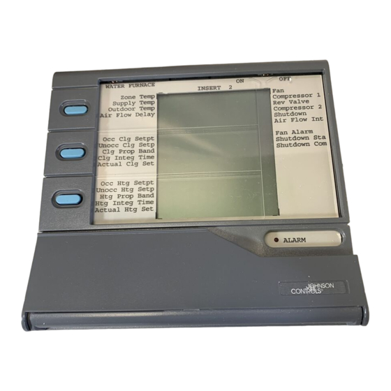
Zone Terminal
flat-head screwdriver
needle-nose pliers
drill
The ZT unit measures 6.88 x 7.31 x 1.52 inch (175 x 186 x 39 mm), and
weighs 1.25 lb (0.57 kg). A coiled, 6-pin telephone-type cord is included.
The cord is 17 inches long and stretches to 5 feet. The ZT contains a
5-year lithium battery, factory installed.
The Wall Mount Base with ZT measures 6.94 x 7.44 x 2.00
(176 x189 x 51 mm).
The Utility Mount Base with ZT measures 6.94 x 7.44 x 6.00
(176 x 189 x 152 mm) when mounted on the ENC100.
Installation of the Zone Terminal must meet the following standards:
Ambient operating conditions: 32 to 122°F (0 to 50°C)
10 to 90% non-condensing relative humidity
86°F (30°C) maximum dew point
Notes:
Do not mount the Zone Terminal on a vibrating surface.
The atmosphere must be free of corrosive chemical vapors that
may damage electronic equipment.
Use mild soap and water with a soft cloth to wipe surfaces of the ZT
clean.
Do not immerse the ZT unit in water.
Wipe clean with pure isopropyl alcohol, if surface becomes
excessively dirty.
Installation Sheet
Issue Date 0495
1
Advertisement

Related Manuals for Johnson Controls METASYS Series

Summary of Contents for Johnson Controls METASYS Series
- Page 1 Use mild soap and water with a soft cloth to wipe surfaces of the ZT Surfaces clean. Do not immerse the ZT unit in water. Wipe clean with pure isopropyl alcohol, if surface becomes excessively dirty. © 1995 Johnson Controls, Inc. Part No. 24-7534-2...
- Page 2 Before you mount the ZT or connect it to a controller, the clear plastic Installing the insert that describes the displayed values must be in place. Inserts 1. To open the ZT, lay the ZT flat and press the white tab on the top of the ZT while pulling the front cover towards you.
- Page 3 AHU103 Controller FMK 102 Remote RLY100/50 CBLCON-0 M100C TE-6400 conect2 Figure 2: Connecting the Zone Terminal Zone Terminal Installation Sheet 3...
- Page 4 Other remote connections include permanently connecting to a UNT or VAV using the CBLCON-0 and TE-6400 Zone Sensor (Figure 3). + 15 VDC + 15 VDC Connect STAT here. Connect VAV/UNT here. 2 4V AC 2 4V A C T R A C S C O M MO N C OM MO N C OM MO N...
- Page 5 The Zone Terminal can be connected directly to a VAV/UNT through a Zone Sensor without the use of the CBLCON-0 (Figure 4). This is a portable application. Zone Terminal VAV/UNT AS - UNT101-0 0 - 1 0 V D C A LO G O U TP U T A N A L O...
- Page 6 For optimum viewing, mount the top of the ZT 65 inches from the floor. Physical Installation of Wall Mountings and Bases Before attaching the Enclosure Kit (ENC100-0) to the wall, remove the Enclosure Kit top or bottom rectangular knockouts with a needle-nose pliers, depending and Base on the end through which the wires will run.
- Page 7 Attach the Enclosure Kit (ENC100-0) to a flat surface or wall for direct connection of the ZT to an application specific controller. Pull wire through before attaching standoffs and screws for the plastic base. MT&BASE Figure 6: Attaching the Enclosure Kit and Utility Mounting Base Zone Terminal Installation Sheet 7...
- Page 8 Attach the base, pulling the telephone jack type cord through the opening as shown below. Plug the cord into the back of the ZT, and snap the ZT into position. ENCMTBAS Figure 7: Connecting and Mounting the ZT 8 Zone Terminal Installation Sheet...
- Page 9 Wall Mount For office or other types of remote connections, attach the Wall Mount to Installation a flat surface or wall. Use three screws and plastic anchors (not provided). For easy reading, mount the ZT at least 65 inches from the floor to the top of the ZT.
- Page 10 Mounting the ZTU Using the wall mounting base, follow the instructions below to mount the Externally on the Zone Terminal on a UPM. M E TA S Y S Zone AHU103 Zone Terminal Mounted on the Outside A LA R M ztcontr Figure 9: Mounting the Zone Terminal on a UPM 1.
- Page 11 ZT, thereby maximizing the use of the UPM. Contact the Panel Unit for more information. Johnson Controls Panel Unit wires and configures units, complete with accessories, to your specifications. The ZTU internal mounting bracket is also available. Contact:...
- Page 12 Use a large flat-head screwdriver and insert it in the bottom where the ZT Removing a and mounting base come together. Gently pry the ZT out of the mounting Mounted ZT base. As you push the screwdriver in, the ZT slides up and then out. REMOVAL Figure 11: Removing Mounted ZT Controls Group...
Need help?
Do you have a question about the METASYS Series and is the answer not in the manual?
Questions and answers