Table of Contents
Advertisement
Advertisement
Table of Contents

Subscribe to Our Youtube Channel
Related Manuals for IFM Electronic efector 300 SI5004


Summary of Contents for IFM Electronic efector 300 SI5004
- Page 1 Operating instructions Flow monitors SI5004...
-
Page 2: Table Of Contents
Contents 1 Safety instructions ������������������������������������������������������������������������ 3 2 Functions and features ����������������������������������������������������������������� 4 2�1 Application area ������������������������������������������������������������������������ 4 2�2 Operating principle flow monitoring ������������������������������������������� 4 3 Installation ������������������������������������������������������������������������������������ 5 3�1 Installation location �������������������������������������������������������������������� 5 3�2 Sources of interference in the pipe system ������������������������������� 6 3�3�... -
Page 3: Safety Instructions
Preliminary note • An instruction is indicated by “►”: Example: ► Check whether the unit operates correctly� • A reaction to the action is indicated by ">": Example: > LED 9 lights� 1 Safety instructions • Please read the product description prior to set-up of the unit� Ensure that the product is suitable for your application without any restrictions�... -
Page 4: Functions And Features
2 Functions and features 2.1 Application area The unit monitors the flow of liquid media� 2.2 Operating principle flow monitoring • The unit detects the flow speed to the calorimetric measuring principle and converts it into an analog output signal (4���20 mA)� The output signal corresponds to the characteristic curve of the sensor�... -
Page 5: Installation
3 Installation Using process adapters the unit can be adapted to different process connections� • Adapters have to be ordered separately as accessories� A correct fit of the unit and ingress resistance of the connection are only ensured using ifm adapters� •... -
Page 6: 3�2 Sources Of Interference In The Pipe System
3.2 Sources of interference in the pipe system Components integrated in the pipes, bends, valves, reductions, etc� lead to turbu- lence of the medium� This affects the function of the unit� Recommendation: Adhere to the distances between sensor and sources of interference: 5...10 x D 3...5 x D... -
Page 7: Electrical Connection
4 Electrical connection The unit must be connected by a qualified electrician� The national and international regulations for the installation of electrical equipment must be adhered to� Voltage supply to EN 50178, SELV, PELV� ► Disconnect power� ► Connect the unit as follows: 1 BN n.c. -
Page 8: Set-Up And Settings For Water
6 Set-up and settings for water (For media other than water → 7�1: Low flow adjustment)� ► Switch on the supply voltage� > All LEDs light and go out again step by step� The unit is in the operating mode� ►... -
Page 9: Additional Settings (Optional)
7 Additional settings (optional) 7.1 Low flow adjustment If the unit is used in media other than water, you should additionally adapt the unit to the minimum flow� Note: The following adjustment must only be carried out after the high flow adjust- ment�... -
Page 10: Error During Adjustment
8 Error during adjustment If no adjustment is possible, all LEDs flash red� The unit then passes into the operating mode with unchanged values� Possible cause /aid: ► Read chapter 3 Installation� Error during installation� Check whether all requirements have been met�... -
Page 11: Maintenance
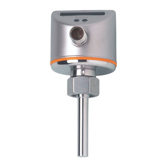
10 Maintenance Recommended maintenance: ► Check the sensor tip for build-up from time to time� ► Clean it using a soft cloth� Stubborn build-up (e�g� lime) can be removed using a common vinegar cleaning agent� 11 Scale drawing 1: LED bar display 2: set button 3: tightening torque 25 Nm... -
Page 12: Technical Data
12 Technical data Application area ���������������������������������������������������������������������������������������������������������� liquids Operating voltage [V] ������������������������������������������������������������������������������������������19���36 DC Analog output [mA] �����������������������������������������������������������������������������������������4���20, max�22 Max� load [Ω] �������������������������������������������������������������������������������������������������������������������500 Current consumption [mA] ���������������������������������������������������������������������������������������������< 60 Power-on delay time [s] ���������������������������������������������������������������������� 10, optically indicated Liquids Medium temperature [°C] ������������������������������������������������������������������������������������ -25 ��� +80 Setting range [cm/s]��������������������������������������������������������������������������������������������������3 ���...
Need help?
Do you have a question about the efector 300 SI5004 and is the answer not in the manual?
Questions and answers