Table of Contents
Advertisement
Quick Links
Advertisement
Table of Contents

Subscribe to Our Youtube Channel
Related Manuals for IFM Electronic efector 300 SU9004


Summary of Contents for IFM Electronic efector 300 SU9004
- Page 1 Operating instructions Ultrasonic flow rate sensor SU9004...
-
Page 2: Table Of Contents
Contents 1 Preliminary note ���������������������������������������������������������������������������������������������������4 1�1 Symbols used ������������������������������������������������������������������������������������������������4 2 Safety instructions �����������������������������������������������������������������������������������������������4 3 Functions and features ����������������������������������������������������������������������������������������5 4 Function ���������������������������������������������������������������������������������������������������������������5 4�1 Processing of the measured signals ��������������������������������������������������������������5 4�2 Volumetric flow monitoring �����������������������������������������������������������������������������5 4�3 Monitoring of temperatures ����������������������������������������������������������������������������5 4�4 Volumetric flow or temperature monitoring / analogue function ��������������������5 4�5 Customer-specific calibration ������������������������������������������������������������������������6 5 Installation������������������������������������������������������������������������������������������������������������7 5�1 Installation location ����������������������������������������������������������������������������������������7... - Page 3 9�4�8 Selection of the medium to be monitored �������������������������������������������17 9�5 Service-Funktionen ��������������������������������������������������������������������������������������17 9�5�1 Reading the min�/max� values for volumetric flow ������������������������������17 9�5�2 Reading the min�/max� values for temperature �����������������������������������17 9�5�3 Reset all parameters to the factory setting �����������������������������������������18 10 Operation ���������������������������������������������������������������������������������������������������������18 10�1 Read the set parameters ���������������������������������������������������������������������������18 10�2 Changing the display unit in the Run mode �����������������������������������������������18 10�3 Error indication ������������������������������������������������������������������������������������������19...
-
Page 4: Preliminary Note
1 Preliminary note 1.1 Symbols used ► Instruction > Reaction, result […] Designation of buttons, switches or indications → Cross-reference Important note Non-compliance can result in malfunctions or interference� 2 Safety instructions • Please read this document prior to installing the unit� Ensure that the product is suitable for your application without any restrictions�... -
Page 5: Functions And Features
3 Functions and features The unit monitors liquids� It detects the 2 process categories volumetric flow and medium temperature� Applications: • Water • Glycol solutions • Oils (viscosity: ≤ 68 mm²/s at 40°C) Selection of the medium to be monitored → 9�4�8� 4 ... -
Page 6: 4�5 Customer-Specific Calibration
Eexample volumetric flow monitoring Factory setting Measuring range scaled I [mA] I [mA] MEW = final value of the measuring range In the set measuring range the output signal is between 4 and 20 mA� It is also indicated: Volumetric flow above the measuring range: output signal > 20 mA� 4.5 ... -
Page 7: Installation
5 Installation 5.1 Installation location ► Install the unit in that section of the plant where the medium flows under pres- sure� This avoids disturbance by air bubbles� ► Install the unit so that the measuring pipe is always completely filled� Arrange for inlet and outlet pipe lengths�... - Page 8 ► Avoid the following installation locations: • Directly in front of a falling pipe� • In a falling pipe� F = flow direction • At the highest point of the pipe system� • Directly in front of the spout of a pipe� F = flow direction •...
-
Page 9: 5�2 Installation Position
5.2 Installation position Avoid the following installation position: flow direction horizontal, unit vertical, connector upwards� There is the risk of build-up of air bubbles� This can affect the measuring accuracy� F = flow direction 5.3 Installation in pipes The unit is installed in the pipe using adapters� Adapters have to be ordered sepa- rately as accessories�... -
Page 10: 5�4 Protection Against High Medium Temperatures
5.4 Protection against high medium temperatures For medium temperatures over 50 °C (122 °F) some parts of the housing can heat up to over 65 °C (140 °F)� ► Protect the housing against contact with flammable substances and uninten- tional contact� 6 Electrical connection The unit must be connected by a qualified electrician� The national and international regulations for the installation of electrical equipment must be adhered to�... -
Page 11: Operating And Display Elements
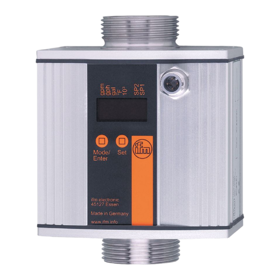
7 Operating and display elements 1 2 3 4 5 6 7 8 Mode /Enter 1 to 8: Indicator LEDs - LED 1 = current volumetric flow in litres/minute� - LED 2 = current volumetric flow in cubic metres/hour� - LED 3 = current volumetric flow in gallons per minute (gpm)� - LED 4 = current volumetric flow in gallons per hour (gph)�... -
Page 12: Menu
8 Menu 8.1 Menu structure l/min °C/°F °C/°F = [Mode/Enter] = [Set] In the Run mode, different display units are accessible (depending on the setting of the parameters [SELd], [Uni�F] and [Uni�T], → 10�2)�... -
Page 13: 8�2 Explanation Of The Menu
8.2 Explanation of the menu ASP1 Analogue start value for temperature� AEP1 Analogue end value for temperature� ASP2 Analogue start value for volumetric flow� AEP2 Analogue end value for volumetric flow� Extended functions / opening of menu level 2� HI�F Maximum value memory for volumetric flow� LO�F Minimum value memory for volumetric flow�... -
Page 14: Parameter Setting
9 Parameter setting During parameter setting the unit remains in the operating mode� It continues its monitoring function with the existing parameters until the parameter setting has been completed� 9.1 General parameter setting 3 steps must be taken for each parameter set: Parameter selection Mode / ►... - Page 15 • Change from menu level 1 to menu level 2 ► Press [Mode/Enter] until [EF] is displayed� Mode /Enter ► Press [Set] briefly� Mode / Enter > The first parameter of the sub-menu is displayed (here: [HI�F])� • Locking / unlocking The unit can be locked electronically to prevent unintentional wrong settings�...
-
Page 16: 9�2 Scaling Of The Analogue Value For Temperature
9.2 Scaling of the analogue value for temperature ► Select [ASP1] and set the value at which 4 mA is provided� ► Select [AEP1] and set the value at which 20 mA is provided� 9.3 Scaling of the analogue value for volumetric flow ► Select [ASP2] and set the value at which 4 mA is provided� ►... -
Page 17: 9�4�6 Setting The Damping Of The Measured Values For Volumetric Flow
9.4.6 Setting the damping of the measured values for volumetric flow ► Select [dAP] and the damping constant in seconds (t value 63 %)� 9.4.7 Setting the error behaviour of OUT1 / OUT2 ► Select [FOU1] and determine the value: - [On] = the analogue signal goes to the upper end stop value� - [OFF] = the analogue signal goes to the lower end stop value� ►... -
Page 18: 9�5�3 Reset All Parameters To The Factory Setting
9.5.3 Reset all parameters to the factory setting [----] is dis- ► Select [rES], then press [Set] and keep it pressed until played� ► Press [Mode/Enter] briefly� The factory setting is listed at the end of the instructions (→ 13 Factory setting)� It makes sense to write your own settings in this table before executing the function�... -
Page 19: 10�3 Error Indication
10.3 Error indication [OL] Detection zone of volumetric flow or temperature exceeded: measured value between 120 % and 130 % of VMR� [UL] Below the detection zone of temperature: measured value below -10°C� [Err] - Unit faulty / malfunction� - Measured value greater than 130 % of VMR� [SEnS] Sensor indicates incorrect measurement�... -
Page 20: Scale Drawing
11 Scale drawing 80,5 Dimensions are in millimeters 12 Technical data Applications: ������������������������������������������������������������������liquids (water, glycol solutions, oils) Operating voltage [V] ������������������������������������������������������������������������������������������19���30 DC Current consumption [mA] ������������������������������������������������������������������������������������100 (24 V) Analogue output ������������������������������������������������������4���20 mA; measuring range scaleable Max� load [Ω] �������������������������������������������������������������������������������������������������������������������500 Power-on delay time [s] �����������������������������������������������������������������������������������������������������10... - Page 21 Flow monitoring l/min m³/h Measuring range 0�0���200�0 0�00���12�00 0�00���52�84 0���3170 Resolution 0�1 0�01 0�02 Display range 0�0���240�0 0�00���14�40 0�00���63�42 0���3804 Maximum permissible flow rate 13,2 58,12 3487 Response time [ms] ������������������������������������������������������������������������������������ < 250 (dAP = 0) Damping flow signal (dAP) [s] ��������������������������������������������������������������������������������� 0�0���1�0 Start-up delay [s] ����������������������������������������������������������������������������������������������������������0���50 Accuracy - water ������������������������������������������������������������������...
-
Page 22: 12�1 Setting Ranges
Operating temperature [°C] �������������������������������������������������������������������������������������� -10���60 Medium temperature [°C] ����������������������������������������������������������������������������������������� -10���80 Pressure resistance [bar]���������������������������������������������������������������������������������������������������16 Material (wetted parts) ������������������stainless steel 316L / 1�4404; Viton; PPS; Centellen 200 Housing materials �������������������������������������������housing: AlMgSi0�5 anodised; sealing: Viton; connector housing: brass Optalloy-plated; PA 6�6; cover film: polyamide Protection ���������������������������������������������������������������������������������������������������������������... -
Page 23: Factory Setting
13 Factory setting Factory setting User setting -10.0 ASP1 80.0 AEP1 ASP2 200.0 AEP2 FOU1 FOU2 Lmin Uni.F °C Uni.T FLOW SELd MEDI More information at www�ifm�com...
Need help?
Do you have a question about the efector 300 SU9004 and is the answer not in the manual?
Questions and answers