Table of Contents
Advertisement
Quick Links
Advertisement
Table of Contents

Subscribe to Our Youtube Channel
Related Manuals for IFM Electronic efector 300 SU9001


Summary of Contents for IFM Electronic efector 300 SU9001
- Page 1 Operating instructions Ultrasonic flow rate sensor SU9001...
-
Page 2: Table Of Contents
Contents 1 Preliminary note ���������������������������������������������������������������������������������������������������4 1�1 Symbols used ������������������������������������������������������������������������������������������������4 2 Safety instructions �����������������������������������������������������������������������������������������������4 3 Functions and features ����������������������������������������������������������������������������������������5 4 Function ���������������������������������������������������������������������������������������������������������������5 4�1 Processing of the measured signals ��������������������������������������������������������������5 4�2 Volumetric flow monitoring �����������������������������������������������������������������������������5 4�3 Consumed quantity monitoring (totalizer function) ����������������������������������������6 4�3�1 Consumed quantity monitoring with pulse output ���������������������������������6 4�3�2 Consumed quantity monitoring with preset meter ��������������������������������6 4�4 Monitoring of temperatures ����������������������������������������������������������������������������6... - Page 3 9�3�1 Settings for quantity monitoring by pulse output ���������������������������������20 9�3�2 Settings for quantity monitoring using the preset meter ��������������������21 9�3�3 Settings for meter reset controlled by the program ����������������������������21 9�3�4 Switch off the meter reset �������������������������������������������������������������������21 9�3�5 Settings for meter reset by an external signal ������������������������������������21 9�4 Settings for temperature monitoring ������������������������������������������������������������21 9�4�1 Settings for limit value monitoring with OUT2 �������������������������������������21 9�4�2 Scaling of the analogue value for temperature �����������������������������������22...
-
Page 4: Preliminary Note
1 Preliminary note 1.1 Symbols used ► Instruction > Reaction, result […] Designation of buttons, switches or indications → Cross-reference Important note Non-compliance can result in malfunctions or interference� 2 Safety instructions • Please read this document prior to installing the unit� Ensure that the product is suitable for your application without any restrictions�... -
Page 5: Functions And Features
3 Functions and features The unit monitors liquids� It detects the 3 process categories volumetric flow, consumed quantity, medium temperature� Applications: • Water • Glycol solutions • Oils (viscosity: viscosity: ≤ 68 cSt at 104°F / ≤ 68 mm²/s at 40°C) Selection of the medium to be monitored → 9.5.9. 4 Function 4.1 Processing of the measured signals • The unit displays the current process values� • It generates 2 output signals according to the parameter setting�... -
Page 6: 4�3 Consumed Quantity Monitoring (Totalizer Function)
4.3 Consumed quantity monitoring (totalizer function) The unit has an internal quantity meter which continuously totals the volumetric flow� The sum corresponds to the current consumed quantity since the last reset� • The current meter count can be indicated� • In addition the value before the last reset is stored� This value can also be indicated�... -
Page 7: 4�5 Volumetric Flow Or Temperature Monitoring / Switching Function
4.5 Volumetric flow or temperature monitoring / switching function OUTx changes its switching state if it is above or below the set switching limits (SPx, rPx)� The following switching functions can be selected: • Hysteresis function / normally open (fig� 1): [OUx] = [Hno]� • Hysteresis function / normally closed (fig�... - Page 8 Voltage output 0 ��� 10 V (example volumetric flow monitoring) Factory setting Measuring range scaled U [V] U [V] MEW = final value of the measuring range In the set measuring range the output signal is between 0 and 10 V� It is also indicated: Volumetric flow above the measuring range: output signal >...
-
Page 9: 4�7 Start-Up Delay [Dst]
4.7 Start-up delay [dSt] If the start-up delay is active ([dSt] > [0]), note: as soon as the volumetric flow quantity exceeds 0�5 % of the final value of the measuring range (VMR), the fol- lowing processes are carried out: • The start-up delay is activated�... -
Page 10: 4�8 Customer-Specific Calibration
Example: dSt for window function 0,5% 1 Volumetric flow quantity Q reaches 0.5% of VMR → dSt starts, output becomes active. 2 dSt elapsed, Q reached good range → output remains active. 3 Q above SP (leaves good range) → output is reset. 4 Q again below SP → output becomes active again. 5 Q below rP (leaves good range) → output is reset again. 6 Q reaches again 0.5 % of VMR → dSt starts, output becomes active. 7 dSt elapsed, Q has not reached good range → output is reset. 8 Q reaches good range → output becomes active. 4.8 Customer-specific calibration This calibration changes the slope of the curve of measured values� It influences the display and the outputs� operating value for display and output signals 140% MEW... -
Page 11: Installation
5 Installation 5.1 Installation location ► Install the unit in that section of the plant where the medium flows under pres- sure� This avoids disturbance by air bubbles� ► Install the unit so that the measuring pipe is always completely filled� Arrange for inlet and outlet pipe lengths�... - Page 12 ► Avoid the following installation locations: • Directly in front of a falling pipe� • In a falling pipe� F = flow direction • At the highest point of the pipe system� • Directly in front of the spout of a pipe� F = flow direction • On the suction side of a pump�...
-
Page 13: 5�2 Installation Position
5.2 Installation position Avoid the following installation position: flow direction horizontal, unit vertical, connector upwards� There is the risk of build-up of air bubbles� This can affect the measuring accuracy� F = flow direction 5.3 Installation in pipes The unit is installed in the pipe using adapters� Adapters have to be ordered sepa- rately as accessories�... -
Page 14: 5�4 Protection Against High Medium Temperatures
5.4 Protection against high medium temperatures For medium temperatures over 122 °F some parts of the housing can heat up to over 140 °F. ► Protect the housing against contact with flammable substances and uninten- tional contact� 6 Electrical connection The unit must be connected by a qualified electrician� The national and international regulations for the installation of electrical equipment must be adhered to�... -
Page 15: Operating And Display Elements
7 Operating and display elements 1 2 3 4 5 6 7 8 Mode /Enter 1 to 8: Indicator LEDs - LED 1 = current volumetric flow in gallons per minute (gpm)� - LED 2 = current volumetric flow in gallons per hour (gph)� - LED 3 = current consumed quantity since the last reset in gallons (gal)�... -
Page 16: Menu
8 Menu 8.1 Menu structure gal* °F = [Mode/Enter] / = [Set] gal = current meter in gal; gal* = stored meter in gal... -
Page 17: 8�2 Explanation Of The Menu
8.2 Explanation of the menu SP1/rP1 Maximum / minimum value for volumetric flow� ImPS Pulse value� Pulse repetition active (= function pulse output) or not active (= function preset ImPR meter)� Output function for OUT1 (volumetric flow or consumed quantity): - Switching signal for limit values: hysteresis function or window function, normally open or normally closed�... -
Page 18: Parameter Setting
9 Parameter setting During parameter setting the unit remains in the operating mode� It continues its monitoring function with the existing parameters until the parameter setting has been completed� 9.1 General parameter setting 3 steps must be taken for each parameter set: Parameter selection ►... - Page 19 • Change from menu level 1 to menu level 2 ► Press [Mode/Enter] until [EF] is displayed� Mode /Enter ► Press [Set] briefly� > The first parameter of the sub-menu is displayed (here: [HI])� Mode /Enter • Locking / unlocking The unit can be locked electronically to prevent unintentional wrong settings�...
-
Page 20: 9�2 Settings For Volumetric Flow Monitoring
9.2 Settings for volumetric flow monitoring 9.2.1 Settings for limit value monitoring with OUT1 ► Select [OU1] and set the switching function: [Hno] = hysteresis function/normally open, [Hnc] = hysteresis function/normally closed, [Fno] = window function/normally open, [Fnc] = window function/normally closed� ►... -
Page 21: 9�3�2 Settings For Quantity Monitoring Using The Preset Meter
9.3.2 Settings for quantity monitoring using the preset meter ► Select [OU1] and set [ImP]� ► Select [ImPS] and set the volumetric flow quantity at which output 1 switches (→ 9.7). ► Select [ImPR] and set [no] > Pulse repetition is not active� The output switches ON if the value set in [ImPS] is reached�... -
Page 22: 9�4�2 Scaling Of The Analogue Value For Temperature
9.4.2 Scaling of the analogue value for temperature ► Select [SEL2] and set [TEMP]� ► Select [OU2 ] and set the function: [I] = current signal proportional to temperature (4…20 mA); [U] = voltage signal proportional to temperature (0…10 V)� ►... -
Page 23: 9�5�5 Calibration Reset
9.5.5 Calibration reset ► [Select [CAr]� ► Press [Set] and keep it pressed until [----] is displayed� ► Press [Mode/Enter] briefly� > Value is reset (CGA = 100)� 9.5.6 Setting the start-up delay ► Select [dSt] and set the numerical value in seconds� 9.5.7 Setting the damping of the measured values ►... -
Page 24: 9�6�2 Reset All Parameters To The Factory Setting
9.6.2 Reset all parameters to the factory setting [----] is dis- ► Select [rES], then press [Set] and keep it pressed until played� ► Press [Mode/Enter] briefly� The factory setting is listed at the end of the instructions (→ 13 Factory setting)� It makes sense to write your own settings in this table before executing the function�... - Page 25 ► Press [Set] and The flashing digit is increased, 9 is followed by 0 and the digit keep it pressed� following on the left becomes active� 8 1� 8 3 [Set] permanently pressed 8 1� 9 3 [Set] kept pressed 8 1� 0 3 If digit 1 is increased this way, the display changes to the next higher setting range (9 is followed by 10, the decimal point is moved one place to the right or the LED display changes)�...
-
Page 26: Operation
10 Operation After power on and expiry of the power-on delay time (approx� 10 s) the unit is in the Run mode (= normal operating mode)� It carries out its measurement and eval- uation functions and generates output signals according to the set parameters� • Operation indication → chapter 7 Controls and indicating elements. -
Page 27: 10�3 Error Indication
10.3 Error indication [SC1] Short circuit in OUT1� [SC2] Short circuit in OUT2� [SC] Short circuit in both outputs� [OL] Detection zone of volumetric flow or temperature exceeded: measured value between 120 % and 130 % of VMR� [UL] Below the detection zone of temperature: measured value below 14°F. -
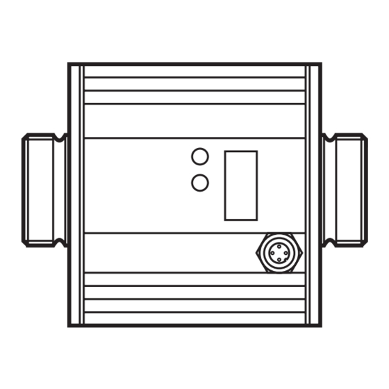
Page 28: Scale Drawing
11 Scale drawing 80,5 Dimensions are in millimeters 12 Technical data Applications: ������������������������������������������������������������������������������� water, glycol solutions, oils Operating voltage [V] ������������������������������������������������������������������������������������������19���30 DC Current rating [mA] ����������������������������������������������������������������������������������������������������2 x 250 Protection: short circuit, reverse polarity, overload Voltage drop [V] ����������������������������������������������������������������������������������������������������������������< 2 Current consumption typ� [mA] ����������������������������������������������������������������������������������������100 Analogue output ���������������������������������������4���20 mA / 0���10 V;... - Page 29 Flow monitoring Measuring range 0�00���52�84 0���3170 Resolution 0�02 Display range 0�00���63�40 0���3804 Maximum permissible 63�4 3804 flow rate Response time [ms] ������������������������������������������������������������������������������������ < 250 (dAP = 0) Damping flow signal (dAP) [s] ��������������������������������������������������������������������������������� 0�0���1�0 Start-up delay [s] ����������������������������������������������������������������������������������������������������������0���50 Accuracy - water ������������������������������������������������������������������ < ± (3% MV + 0�2% MVR) - glycol solutions (35%) ����������������������������������������...
-
Page 30: 12�1 Setting Ranges
Operating temperature [°F] ���������������������������������������������������������������������������������������14���140 Medium temperature [°F] ������������������������������������������������������������������������������������������14���176 Pressure resistance [bar/psi] ��������������������������������������������������������������������������������������16/232 Material (wetted parts) ������������������stainless steel 316L / 1�4404; Viton; PPS; Centellen 200 Housing materials �������������������������������������������housing: AlMgSi0�5 anodised; sealing: Viton; connector housing: brass Optalloy-plated; PA 6�6; cover film: polyamide Protection ��������������������������������������������������������������������������������������������������������������� IP 67 / III Insulation resistance [MΩ] ������������������������������������������������������������������������... -
Page 31: Factory Setting
13 Factory setting Factory setting User setting 8.00 4.00 0.02 ImPS ImPR 40.00 SP2 (FLOW) 32.00 rP2 (FLOW) 136.5 SP2 (TEMP) 112.0 rP2 (TEMP) 0.00 ASP (FLOW) 52.84 AEP (FLOW) 14.0 ASP (TEMP) 176.0 AEP (TEMP) +EDG Din2 FOU1 FOU2 FLOW SELd FLOW...
Need help?
Do you have a question about the efector 300 SU9001 and is the answer not in the manual?
Questions and answers