Table of Contents
Advertisement
Quick Links
Advertisement
Table of Contents

Subscribe to Our Youtube Channel
Related Manuals for IFM Electronic efector 300 SU8200


Summary of Contents for IFM Electronic efector 300 SU8200
- Page 1 Operating instructions Ultrasonic flow rate sensor SU8200...
-
Page 2: Table Of Contents
Contents 1 Preliminary note ���������������������������������������������������������������������������������������������������3 1�1 Symbols used ������������������������������������������������������������������������������������������������3 2 Safety instructions �����������������������������������������������������������������������������������������������3 3 Functions and features ����������������������������������������������������������������������������������������4 4 Function ���������������������������������������������������������������������������������������������������������������4 4�1 Processing of the measured signals ��������������������������������������������������������������4 4�2 Volumetric flow monitoring �����������������������������������������������������������������������������4 4�3 Monitoring of temperatures ����������������������������������������������������������������������������4 4�4 Switching function ������������������������������������������������������������������������������������������4 4�5 Start-up delay [dSt] ����������������������������������������������������������������������������������������5 4�6 Customer-specific calibration (CGA) �������������������������������������������������������������7 5 Installation������������������������������������������������������������������������������������������������������������8... -
Page 3: Preliminary Note
9�4�9 Selection of the medium to be monitored �������������������������������������������19 9�5 Service functions �����������������������������������������������������������������������������������������19 9�5�1 Reading the min�/max� values for volumetric flow ������������������������������19 9�5�2 Reset all parameters to the factory setting �����������������������������������������19 10 Operation ���������������������������������������������������������������������������������������������������������20 10�1 Read the set parameters ���������������������������������������������������������������������������20 10�2 Changing the display unit in the Run mode �����������������������������������������������20 10�3 Error indication ������������������������������������������������������������������������������������������21 10�4 General operating conditions ���������������������������������������������������������������������21... -
Page 4: Functions And Features
3 Functions and features The unit monitors liquids� It detects the 2 process categories volumetric flow and medium temperature� Applications: • Water • Glycol solutions • Oils (viscosity: ≤ 68 mm²/s at 40°C) Selection of the medium to be monitored → 9�4�9� 4 ... -
Page 5: 4�5 Start-Up Delay [Dst]
• Window function / normally closed (fig� 2): [OUx] = [Fnc]� The width of the window can be set by means of the distance between SPx and rPx� SPx = maximum value, rPx = minimum value� HY = hysteresis; FE = window; examples for volumetric flow monitoring When set to the window function the set and reset points have a fixed hysteresis of 0�25 % of the final value of the measuring range�... - Page 6 Example: dSt for hysteresis function 0,5% 1 Volumetric flow quantity Q reaches 0�5% of VMR → dSt starts, output becomes active� 2 dSt elapsed, Q reached SP → output remains active� 3 Q below SP, but above rP → output remains active� 4 Q below rP →...
-
Page 7: 4�6 Customer-Specific Calibration (Cga)
Example: dSt for window function 0,5% 1 Volumetric flow quantity Q reaches 0�5% of VMR → dSt starts, output becomes active� 2 dSt elapsed, Q reached good range → output remains active� 3 Q above SP (leaves good range) → output is reset� 4 Q again below SP →... -
Page 8: Installation
5 Installation 5.1 Installation location ► Install the unit in that section of the plant where the medium flows under pres- sure� This avoids disturbance by air bubbles� ► Install the unit so that the measuring pipe is always completely filled� ►... - Page 9 ► Avoid the following installation locations: • Directly in front of a falling pipe� • In a falling pipe� FF = flow direction • At the highest point of the pipe system� • Directly in front of the spout of a pipe� F = flow direction •...
-
Page 10: 5�2 Installation In Pipes
5.2 Installation in pipes The unit is installed in the pipe using adapters� Adapters have to be ordered sepa- rately as accessories� Order no� E40179: 2 adapters for R½ pipes, stainless steel + 2 seals� Order no� E40180: 2 adapters for R¾ pipes, stainless steel + 2 seals� Order no�... -
Page 11: 5�3 Protection Against High Medium Temperatures
5.3 Protection against high medium temperatures For medium temperatures over 50 °C (122 °F) some parts of the housing can heat up to over 65 °C (140 °F)� ► Protect the housing against contact with flammable substances and unintentional contact� 6 Electrical connection The unit must be connected by a qualified electrician� The national and international regulations for the installation of electrical equipment must be adhered to�... -
Page 12: Operating And Display Elements
7 Operating and display elements 1 2 3 4 5 6 7 8 Mode /Enter 1 to 8: Indicator LEDs -LED 1 = current volumetric flow in litres/minute� -LED 2 = current volumetric flow in cubic metres/hour� -LED 3 = current volumetric flow in gallons per minute (gpm)� -LED 4 = current volumetric flow in gallons per hour (gph)�... -
Page 13: Menu
8 Menu 8.1 Menu structure l/min °C °F = [Mode/Enter] / = [Set]... -
Page 14: 8�2 Explanation Of The Menu
8.2 Explanation of the menu SP1/rP1 Maximum / minimum value for volumetric flow� Output function for OUT1 (volumetric flow): - Switching signal for limit values: hysteresis function or window function, normally open or normally closed� Output function for OUT2 (volumetric flow or temperature): - Switching signal for limit values: hysteresis function or window function, normally open or normally closed�... -
Page 15: Parameter Setting
9 Parameter setting During parameter setting the unit remains in the operating mode� It continues its monitoring function with the existing parameters until the parameter setting has been completed� 9.1 General parameter setting 3 steps must be taken for each parameter set: Parameter selection ►... - Page 16 • Change from menu level 1 to menu level 2 ► Press [Mode/Enter] until [EF] is displayed� Mode /Enter ► Press [Set] briefly� > The first parameter of the sub-menu is displayed (here: [HI])� Mode /Enter • Locking / unlocking The unit can be locked electronically to prevent unintentional wrong settings�...
-
Page 17: 9�2 Settings For Volumetric Flow Monitoring
9.2 Settings for volumetric flow monitoring 9.2.1 Settings for limit value monitoring with OUT1 ► Select [OU1] and set the switching function: - [Hno] = hysteresis function/normally open, - [Hnc] = hysteresis function/normally closed, - [Fno] = window function/normally open, - [Fnc] = window function/normally closed� ► Select [SP1] and set the value at which the output switches� ►... -
Page 18: 9�4 User Settings (Optional)
9.4 User settings (optional) 9.4.1 Determine the standard unit of measurement for volumetric flow ► Select [UniF] and set the unit of measurement: [Lmin], [m3h], [GPm] or [GPh]� 9.4.2 Determine the standard unit of measurement for temperature ► Select [UniT] and set the unit of measurement: [°C] or [°F]� 9.4.3 Setting of the display mode ► Select [diS] and determine the update rate and orientation of the display: - [d1] = update of the measured values every 500 ms�... -
Page 19: 9�4�9 Selection Of The Medium To Be Monitored
9.4.9 Selection of the medium to be monitored ► [MEDI] wählen und gewünschtes Medium einstellen: - [H2O] = Water� - [GLYC] = Glycol solutions� - [OIL] = Oils� 9.5 Service functions 9.5.1 Reading the min./max. values for volumetric flow ► Select [HI] or [LO] and press [Set] briefly� [HI] = maximum value, [LO] = minimum value� Delete memory: ►... -
Page 20: Operation
10 Operation After power on and expiry of the power-on delay time (approx� 10 s) the unit is in the Run mode (= normal operating mode)� It carries out its measurement and eval- uation functions and generates output signals according to the set parameters� •... -
Page 21: 10�3 Error Indication
10.3 Error indication [SC1] Short circuit in OUT1� [SC2] Short circuit in OUT2� [SC] Short circuit in both outputs� [OL] Detection zone of volumetric flow or temperature exceeded: measured value between 120 % and 130 % of VMR� [UL] Below the detection zone of temperature: measured value below -10°C�... -
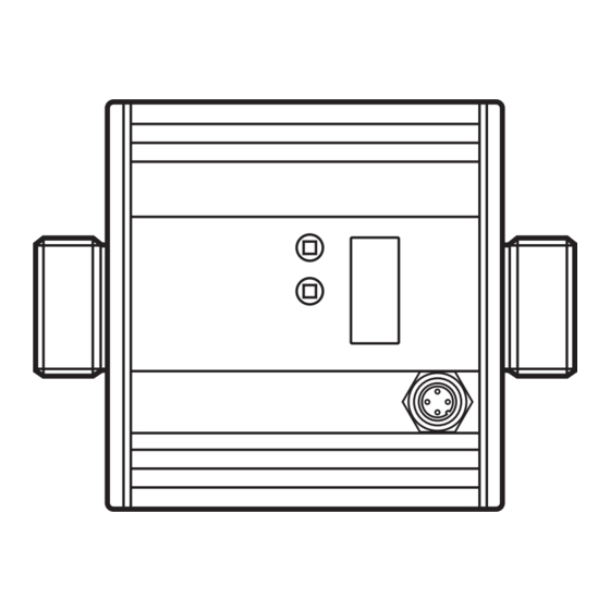
Page 22: Scale Drawing
11 Scale drawing Flow direction 1: Display 2: Connector (electrical connection) 3� Marking direction of flow... -
Page 23: Technical Data
12 Technical data Applications: ������������������������������������������������������������������������������� water, glycol solutions, oils Operating voltage [V] ������������������������������������������������������������������������������������������19���30 DC Current rating [mA] ����������������������������������������������������������������������������������������������������2 x 250 Protection: short circuit, reverse polarity, overload Voltage drop [V] ����������������������������������������������������������������������������������������������������������������< 2 Current consumption typ� [mA] ����������������������������������������������������������������������������������������100 Power-on delay time [s] �����������������������������������������������������������������������������������������������������10 Flow monitoring l/min m³/h... -
Page 24: 12�1 Setting Ranges
Temperature monitoring Measuring range [°C / °F] ��������������������������������������������������������������������� -10���80 / 4�0���176�0 Resolution [°C / °F] ���������������������������������������������������������������������������������������������������0�2 / 0�5 Response time [s] ��������������������������������������������������T09 = 70 (for water, Q > 5 l/min / 1 gpm) Accuracy [°C / °F] ��������������������������������������������������� ± 3 (Q > 1 l/min) / ± 5�4 (Q > 0�26 gpm) Operating temperature [°C / °F] ����������������������������������������������������������������... -
Page 25: Factory Setting
13 Factory setting Factory setting User setting 20.0 10.0 80.0 SP2 (FLOW) 60.0 rP2 (FLOW) 62.0 SP2 (TEMP) 44.0 rP2 (TEMP) FOU1 FOU2 Lmin UniT °C UniF FLOW SEL2 MEDI More information at www�ifm�com...
Need help?
Do you have a question about the efector 300 SU8200 and is the answer not in the manual?
Questions and answers