Table of Contents
Advertisement
Quick Links
Advertisement
Table of Contents

Subscribe to Our Youtube Channel
Related Manuals for IFM Electronic efector 300 SM0505


Summary of Contents for IFM Electronic efector 300 SM0505
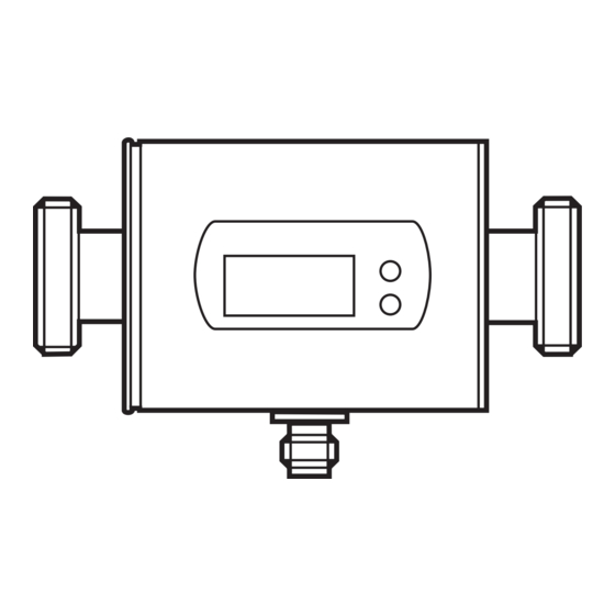
- Page 1 Operating instructions Magnetic-inductive flow sensor SM0505...
-
Page 2: Table Of Contents
Contents Preliminary note ��������������������������������������������������������������������������������������4 1�1 Symbols used ������������������������������������������������������������������������������������������������4 2 Safety instructions �����������������������������������������������������������������������������������������������4 3 Functions and features ����������������������������������������������������������������������������������������5 4 Function ���������������������������������������������������������������������������������������������������������������5 4�1 Processing of the measured signals ��������������������������������������������������������������5 4�2 Volumetric flow monitoring �����������������������������������������������������������������������������5 4�3 Consumed quantity monitoring (totalizer function) ����������������������������������������6 4�3�1 Consumed quantity monitoring with pulse output ���������������������������������7 4�3�2 Consumed quantity monitoring with preset meter ��������������������������������7 4�4 Monitoring of temperatures ����������������������������������������������������������������������������7 4�5 Empty pipe detection �������������������������������������������������������������������������������������7... - Page 3 9�3�2 Settings for quantity monitoring using the preset meter ��������������������22 9�3�3 Settings for meter reset controlled by the program ����������������������������22 9�3�4 Switch off the meter reset �������������������������������������������������������������������22 9�3�5 Settings for meter reset by an external signal �����������������������������������22 9�4 Settings for temperature monitoring ������������������������������������������������������������22 9�4�1 Settings for limit value monitoring with OUT2 �������������������������������������22 9�4�2 Scaling of the analogue value for temperature �����������������������������������23 9�5 User settings (optional) ��������������������������������������������������������������������������������23...
-
Page 4: Preliminary Note
1 Preliminary note 1.1 Symbols used ► Instruction > Reaction, result […] Designation of buttons, switches or indications → Cross-reference Important note Non-compliance can result in malfunctions or interference� 2 Safety instructions • Please read this document prior to installing the unit� Ensure that the product is suitable for your application without any restrictions�... -
Page 5: Functions And Features
3 Functions and features The unit monitors liquids� It detects the 3 process categories volumetric flow, consumed quantity, medium temperature� Application area Conductive liquids with the following properties: • conductivity: ≥ 20 µS/cm • viscosity: < 70 mm /s at 40 °C 4 Function 4.1 Processing of the measured signals • The unit displays the current process values�... -
Page 6: 4�3 Consumed Quantity Monitoring (Totalizer Function)
• Flow = “flow direction”: process value and display positive� • Flow against the “flow direction”: process value and display negative� Only positive process values are processed for the signal output (limit values and analogue values for volumetric flow)� 4.3 Consumed quantity monitoring (totalizer function) The unit has an internal quantity meter which continuously totals the volumetric flow�... -
Page 7: 4�3�1 Consumed Quantity Monitoring With Pulse Output
4.3.1 Consumed quantity monitoring with pulse output Output 1 provides a counting pulse if the value set in [ImPS] is reached (→ 9.3.1). 4.3.2 Consumed quantity monitoring with preset meter 2 types of monitoring are possible: • Time-dependent quantity monitoring - Settings: [ImPS] = quantity x, [ImPR] = [no], [rTO] = time t� - If the quantity x is reached during the time t, output 1 switches and remains switched until the meter is reset�... -
Page 8: 4�6 Volumetric Flow Or Temperature Monitoring / Switching Function
4.6 Volumetric flow or temperature monitoring / switching function OUTx changes its switching state if it is above or below the set switching limits (SPx, rPx)� The following switching functions can be selected: • Hysteresis function / normally open: [OUx] = [Hno]� • Hysteresis function / normally closed: [OUx] = [Hnc]�... - Page 9 Voltage output 0 ��� 10 V (example volumetric flow monitoring) Factory setting Measuring range scaled U [V] U [V] MEW = final value of the measuring range In the set measuring range the output signal is between 0 and 10 V� It is also indicated: Volumetric flow above the measuring range: output signal >...
-
Page 10: 4�8 Start-Up Delay [Dst]
4.8 Start-up delay [dSt] If the start-up delay is active ([dSt] > [0]), note: as soon as the volumetric flow quantity exceeds 0�5 % of the final value of the measuring range (VMR), the fol- lowing processes are carried out: • The start-up delay is activated�... -
Page 11: Installation
Example: dSt for window function 0,5% 1 Volumetric flow quantity Q reaches 0.5% of VMR → dSt starts, output becomes active. 2 dSt elapsed, Q reached good range → output remains active. 3 Q above SP (leaves good range) → output is reset. 4 Q again below SP → output becomes active again. 5 Q below rP (leaves good range) → output is reset again. 6 Q reaches again 0.5 % of VMR → dSt starts, output becomes active. 7 dSt elapsed, Q has not reached good range → output is reset. 8 Q reaches good range, output becomes active� 5 Installation 5.1 Installation location ► Install the unit so that the measuring pipe is always completely filled� ►... - Page 12 ► Install in front of or in a rising pipe� flow direction F = flow direction ► Avoid the following installation locations: • Directly in front of a falling pipe� • In a falling pipe� flow direction F = flow direction • At the highest point of the pipe system�...
- Page 13 The unit can be installed independently of the orientation if the following is ensured: - No air bubbles can form in the pipe system� - The pipes are always completely filled� • On the suction side of a pump� flow direction F = flow direction If installed in an ungrounded pipe system (e�g�...
-
Page 14: 5�2 Installation In Pipes
5.2 Installation in pipes The unit is installed in the pipe using adapters� Adapters have to be ordered sepa- rately as accessories� - Order no� E40179: 2 adapters for R½ pipes + 2 seals)� - Order no� E40180: 2 adapters for R¾ pipes + 2 seals)� flow direction 1�... -
Page 15: Electrical Connection
6 Electrical connection The unit must be connected by a qualified electrician� The national and international regulations for the installation of electrical equipment must be adhered to� Voltage supply to EN50178, SELV, PELV� ► Disconnect power� ► Connect the unit as follows: 1 BN 2 WH OUT2/InD... -
Page 16: Operating And Display Elements
7 Operating and display elements 1 2 3 4 5 6 7 8 Mode / Enter 1 to 8: Indicator LEDs - LED 1 = current volumetric flow in litres/minute� - LED 2 = current volumetric flow in cubic metres/hour� - LED 3 = current consumed quantity since the last reset in litres�... -
Page 17: Menu
8 Menu 8.1 Menu structure l/min °C = [Mode/Enter] / = [Set] l or m = current meter count in l, m or 1000 m l* or m * = stored meter count in l, m or 1000 m... -
Page 18: 8�2 Explanation Of The Menu
8.2 Explanation of the menu SP1/rP1 Maximum / minimum value for volumetric flow� ImPS Pulse value� ImPR Pulse repetition active (= pulse output) or not active (= function preset meter)� Output function for OUT1 (volumetric flow or consumed quantity): - Switching signal for limit values: hysteresis function or window function, normally open or normally closed�... -
Page 19: Parameter Setting
9 Parameter setting During parameter setting the unit remains in the operating mode� It continues its monitoring function with the existing parameters until the parameter setting has been completed� 9.1 General parameter setting 3 steps must be taken for each parameter set: Parameter selection Mode / ►... - Page 20 • Change from menu level 1 to menu level 2: ► Press [Mode/Enter] until [EF] is Mode / displayed� Enter ► Press [Set] briefly� Mode / Enter > The first parameter of the sub-menu is displayed (here: [HI])� • Locking / unlocking The unit can be locked electronically to prevent unintentional wrong settings�...
-
Page 21: 9�2 Settings For Volumetric Flow Monitoring
9.2 Settings for volumetric flow monitoring 9.2.1 Settings for limit value monitoring with OUT1 ► Select [OU1] and set the switching function: - [Hno] = hysteresis function/normally open, - [Hnc] = hysteresis function/normally closed, - [Fno] = window function/normally open, - [Fnc] = window function/normally closed�... -
Page 22: 9�3�2 Settings For Quantity Monitoring Using The Preset Meter
9.3.2 Settings for quantity monitoring using the preset meter ► Select [OU1] and set [ImP]� ► Select [ImPS] and set the volumetric flow quantity at which output 1 switches (→ 9.7). ► Select [ImPR] and set [no]: pulse repetition is not active� The output switches ON if the value set in [ImPS] is reached�... -
Page 23: 9�4�2 Scaling Of The Analogue Value For Temperature
9.4.2 Scaling of the analogue value for temperature ► Select [SEL2] and set [TEMP]� ► Select [OU2 ] and set the function: - [I] = current signal proportional to temperature (4…20 mA); - [U] = voltage signal proportional to temperature (0…10 V)� ►... -
Page 24: 9�5�6 Setting The Damping Of The Measured Values
9.5.6 Setting the damping of the measured values ► Select [dAP] and the damping constant in seconds (t value 63 %)� 9.5.7 Setting the error behaviour of OUT1 / OUT2 ► Select [FOU1] and determine the value: - [On] = output 1 switches ON in case of an error� - [OFF] = output 1 switches OFF in case of an error�... -
Page 25: 9�7 Setting Of The Preset Meter / Pulse Value (Imps)
9.7 Setting of the preset meter / pulse value (ImPS) 7 setting ranges are available: Display in steps of Value 0 0 0� 1 ��� 9 9 9� 9 0�1 l 0�1���999�9 l 1 0 0 0 ��� 9 9 9 9 1000���9999 l 1 0�... - Page 26 ► Press [Set] and The flashing digit is increased, 9 is followed by 0 and the digit keep it pressed� following on the left becomes active� 8 1� 8 3 [Set] permanently pressed 8 1� 9 3 [Set] kept pressed 8 1� 0 3 If digit 1 is increased this way, the display changes to the next higher setting range (9 is followed by 10, the decimal point is moved one place to the right or the LED display changes)�...
-
Page 27: Operation
10 Operation After power on and expiry of the power-on delay time (approx� 5 s) the unit is in the Run mode (= normal operating mode)� It carries out its measurement and eval- uation functions and generates output signals according to the set parameters� • During the power-on delay time the outputs are switched as programmed: ON for NO function (Hno / Fno) and OFF for NC function (Hnc / Fnc)�... -
Page 28: 10�4 General Operating Conditions
10.4 General operating conditions ► Avoid deposits, accumulated gas and air in the pipe system� For medium temperatures over 50 °C some parts of the housing can heat up to over 65 °C� ► In this case do not touch the unit� ►... -
Page 29: Technical Data
12 Technical data Application ����������������������������������������������������������������������������������������������� conductive liquids Conductivity �������������������������������������������������������������������������������������������������������� ≥ 20 µS/cm Viscosity ������������������������������������������������������������������������������������������������ < 70 mm²/s at 40°C Operating voltage [V] ������������������������������������������������������������������������������������������19���30 DC Current rating [mA] ����������������������������������������������������������������������������������������������������2 x 200 protection: short circuit, reverse polarity, overload Voltage drop [V] ����������������������������������������������������������������������������������������������������������������< 2 Current consumption typ� [mA] ����������������������������������������������������������������������������������������120 Analogue output ���������������������������������������4���20 mA / 0���10 V;... -
Page 30: 12�1 Setting Ranges
Temperature monitoring Measuring range [°C]������������������������������������������������������������������������������������������������ -20���80 Response time [s] ������������������������������������������������������������������������������ T09 = 30 (Q > 5 l/min) Resolution [°C]������������������������������������������������������������������������������������������������������������������0�2 Accuracy [°C] ��������������������������������������������������������������������������������������������± 2�5 (Q > 5 l/min) Operating temperature [°C] �������������������������������������������������������������������������������������� -10���60 Medium temperature [°C] ����������������������������������������������������������������������������������������� -10���70 Pressure resistance [bar]���������������������������������������������������������������������������������������������������16 Material (wetted parts) ������������������������... -
Page 31: Factory Setting
13 Factory setting Factory setting User setting 20.00 19.50 ImPS ImPR SP2 (FLOW) 40.00 rP2 (FLOW) 39.50 SP2 (TEMP) 20.0 rP2 (TEMP) 19.6 ASP (FLOW) AEP (FLOW) 100.0 ASP (TEMP) -20.0 AEP (TEMP) 80.0 DIn2 +EDG FOU1 FOU2 Lmin SELd FLOW SEL2 FLOW...
Need help?
Do you have a question about the efector 300 SM0505 and is the answer not in the manual?
Questions and answers