Table of Contents

Related Manuals for IFM Electronic efector 300 SU7200


Summary of Contents for IFM Electronic efector 300 SU7200
- Page 1 Bedienungsanleitung Operating instructions Notice pour utilisateurs ® Ultraschall- Durchflußsensor Ultrasonics flow rate sensor Capteur de débit à ultrasons SU7200 l/min °C °F...
-
Page 2: Table Of Contents
Inhalt Bedien- und Anzeigeelemente ....Seite 5 Bestimmungsgemäße Verwendung ... . . Seite 6 Montage ....... . Seite 8 Elektrischer Anschluß... - Page 3 Menü-Übersicht / Menu structure / Structure du menu °C / °F °C / °F SU7200 Sachnr. 701813/00...
- Page 4 Maßzeichnung / Scale drawing / Dimensions Flow direction Display Display Affichage Steckverbindung (elektrischer Anschluß) Connector (electrical connection) Connecteur (raccordement électrique) Markierung Durchflußrichtung Marking direction of flow Marquage sens du débit...
-
Page 5: Bedien- Und Anzeigeelemente
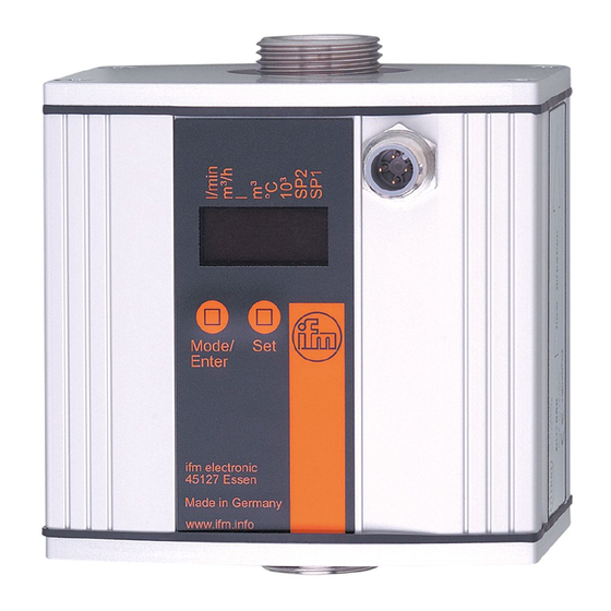
Bedien- und Anzeigeelemente Mode /Enter Leuchtende LED = eingestellte Anzeigeeinheit: 4 x LED grün - Durchflußmenge in l/min, m /h, gallons/min (gpm) oder gallons/h (gph). Anzeigefunktionen - °C: Aktuelle Medientemperatur in °C. 4 x LED gelb - °F: Aktuelle Medientemperatur in °F. - SP1 / SP2: Anzeige des Schaltzustands;... -
Page 6: Bestimmungsgemäße Verwendung
Bestimmungsgemäße Verwendung Das Gerät erfaßt Durchflußmenge und Temperatur von Wasser, • zeigt die aktuellen Prozeßwerte durch ein Display an • und erzeugt 2 Ausgangssignale entsprechend der eingestellten Ausgangskonfiguration. Anzeige • Aktuelle Durchflußmenge in l/min, m /h, gallons/min (gpm) oder gallons/h (gph); 4-stellige Anzeige. Die Anzeigeeinheit wird durch Programmierung festgelegt (→... - Page 7 Druckverlust (dP) in Abhängigkeit von der Durchflußmenge (Q). dP [bar] 0,05 0,04 0,03 0,02 0,01 Q [l/min] 30 40 50 60 80 100 Q [m 0,3 0,4 1,5 2,0 2,5 3 Q [gpm] 20 25 Q [gph] 1200 1500...
-
Page 8: Montage
Montage • Schrauben Sie die Adapter (B) in die Rohrleitung (A) ein. Adapter sind gesondert als Zubehör zu bestellen: Bestell-Nr. E40151 (für Rohrleitung R½). Bestell-Nr. E40154 (für Rohrleitung ½” NPT). Verwenden Abdichtung ausschließlich die mitgelieferten Centellen- dichtungen. • Bauen Sie das Gerät entspre- chend der Durchflußrichtung ein (Pfeil). - Page 9 Elektrischer Anschluß Das Gerät darf nur von einer Elektrofachkraft installiert werden. Befolgen Sie die nationalen und internationalen Vorschriften zur Errichtung elektrotechnischer Anlagen. Spannungsversorgung nach EN50178, SELV, PELV. Um die "limited Voltage" Anforderungen gemäß UL 508 zu erfüllen, muß das Gerät aus einer galvanisch getrennten Quelle versorgt und durch eine Überstromeinrichtung abgesichert werden.
-
Page 10: Programmieren
Programmieren Drücken Sie die Taste Mode/Enter, bis der gewünschte Parameter im Display erscheint. Mode /Enter Drücken Sie die Taste Set und halten Sie sie gedrückt. Der aktuelle Parameterwert wird Mode 5 s lang blinkend angezeigt, /Enter danach wird er erhöht* (schrittweise durch Einzeldruck oder kontinuierlich durch Festhalten der Taste). -
Page 11: Betrieb
Betrieb Prüfen nach Montage, elektrischem Anschluß Programmierung, ob das Gerät sicher funktioniert. Störanzeigen während des Betriebs: Meßwert > 120% des Meßbereichsendwerts. Meßwert < Anfangswert des Meßbereichs. Blinkend: Kurzschluß in Schaltausgang 1 / 2.* Blinkend: Kurzschluß in beiden Schaltausgängen.* Blinkend: Strömungssensor fehlerhaft. Blinkend: Gerät defekt / Funktionsfehler. - Page 12 Das Display zeigt die aktuelle Durchflußmenge an, die gelben LEDs signalisieren den Schaltzustand der Ausgänge. Das Display kann vorübergehend auf Temperaturanzeige umgeschaltet werden (kurz die Taste “Set” drücken; nach 15 s geht das Gerät wieder auf die Anzeigeeinheit zurück, die im Menüpunkt UniF eingestellt wurde). Display-Modus Anzeige der Parameter und der eingestellten Parameterwerte Das Gerät geht durch kurzen Druck auf die Taste “Mode/Enter”...
-
Page 13: Technik-Information / Funktionsweise / Parameter Einstellbare Parameter
Technik-Information / Funktionsweise / Parameter Einstellbare Parameter Schaltpunkt 1 / 2 Oberer Grenzwert, bei dem der Ausgang seinen Schaltzustand ändert. Rückschaltpunkt 1 / 2 Unterer Grenzwert, bei dem der Ausgang seinen Schaltzustand ändert. rPx ist stets kleiner als SPx. Es können nur Werte eingegeben werden, die unter dem Wert für SPx liegen. - Page 14 Erweiterte Funktionen Dieser Menüpunkt enthält ein Untermenü mit weiteren Parametern. Durch kurzen Druck auf die Set-Taste erhalten Sie Zugang zu diesen Parametern. Min-Max-Speicher für Durchfluß • HI: Anzeige der höchsten gemessenen Durchflußmenge • LO: Anzeige der niedrigsten gemessenen Durchflußmenge Löschen des Speichers: - Drücken Sie die “Mode/Enter”-Taste, bis HI oder LO erscheint.
- Page 15 Einstellung der Anzeige Es sind 7 Einstellungen wählbar: • d1 = Meßwertaktualisierung alle 0,5 s. • d2 = Meßwertaktualisierung alle 1 s. • d3 = Meßwertaktualisierung alle 2 s. Die Meßwertaktualisierung betrifft nur die Anzeige. Sie wirkt nicht auf die Ausgänge. •...
- Page 16 Kundenseitige Kalibrierung Anzeige (CGA) Durch kundenseitige Kalibrierung wird die Steigung 60 l/min der Meßwertkurve verändert. 50 l/min Sie beeinflußt die Anzeige und 40 l/min die Ausgänge. Die Steigungsänderung wird in Prozent angegeben. 100% ent- 50 l/min spricht der Werkskalibrierung. A = Meßwertkurve ohne Sie kann zurückgesetzt werden Kalibrierung (→...
- Page 17 Anlaufüberbrückungszeit (dSt) Ist die Anlaufüberbrückungszeit aktiv (dSt > 0), gelten folgende Bedingungen: Sobald Durchflußmenge 0,5% Meßbereichsendwerts (MEW) überschreitet, • wird die Anlaufüberbrückungszeit gestartet, • schaltet Ausgang 1 entsprechend der Programmierung: EIN bei Schließerfunktion (Hno / Fno), AUS bei Öffnerfunktion (Hnc / Fnc), •...
- Page 18 Beispiel: dSt bei Fensterfunktion 0,5% Durchflußmenge Q erreicht 0,5% MEW → dSt startet, Ausgang wird aktiv. dSt abgelaufen, Q hat Gutbereich erreicht → Ausgang bleibt aktiv. Q steigt über SP (verläßt Gutbereich) → Ausgang wird zurückgesetzt. Q fällt wieder unter SP → Ausgang wird wieder aktiv. Q fällt unter rP (verläßt Gutbereich) →...
-
Page 19: Technische Daten
Technische Daten Einsatzbereich ......Durchfluß von Wasser Betriebsspannung [V]....... 20 ... 28 DC Strombelastbarkeit [mA]. -
Page 20: Controls And Indicating Elements
Controls and indicating elements Mode /Enter Lighting LED = set display unit: 4 x LED green - Flow rate in l/min, m /h, gallons/min (gpm) or gallons/h (gph). Display functions - °C: Medium temperature in °C. 4 x LED yellow - °F: Medium temperature in °F. -
Page 21: Function And Features
Function and features The flow rate sensor detects the flow rate of water, and the temperature • indicates the current process values via the display • and generates 2 output signals according to the set output configuration. Display • Current flow rate in l/min, m /h, gallons/min (gpm) or gallons/h (gph);... - Page 22 Pressure loss (dP) is dependent on the flow rate (Q). dP [bar] 0,05 0,04 0,03 0,02 0,01 Q [l/min] 30 40 50 60 80 100 Q [m 0,3 0,4 1,5 2,0 2,5 3 Q [gpm] 20 25 Q [gph] 1200 1500...
-
Page 23: Mounting
Mounting • Screw the adapters (B) into the pipe (A). The adapters have to be ordered separately as acces- sories: Order number E40151 (for R½ pipe). Order number E40154 (for ½” NPT pipe). For sealing only use the sup- plied Centellen seals. •... -
Page 24: Electrical Connection
Electrical connection The unit must be connected by a suitably qualified electrician. The national and international regulations for the installation of electrical equipment must be observed. Voltage supply according to EN50178, SELV, PELV. The device shall be supplied from an isolating source and protected by an overcurrent device such that the limited voltage circuit requirements in accordance with UL 508 are met. -
Page 25: Programming
Programming Press the Mode/Enter pushbutton several times until the requested parameter is displayed. Mode /Enter Press the Set pushbutton and keep it pressed. The current parameter value flashes for 5 s, Mode /Enter then the value is increased* (incremental by pressing briefly or scrolling by holding pressed). -
Page 26: Operation
Operation After mounting, wiring and setting check whether the unit operates correctly. Faults displayed during operation: Measured value > 120% of the final value of the measuring range. Measured value < lowest value of the measuring range. Flashing: short circuit in the switching output 1 / 2.* Flashing: short circuit in both switching outputs.* Flashing: fault in the measuring probe. - Page 27 The display indicates the current measured values, the yellow LEDs signal the switching status of the outputs. The displayed unit can be changed temporarily to indicate the current temper- ature (press the "Set" pushbutton briefly, after 15 s the units returns to the dis- play unit set in the menu point UniF).
-
Page 28: Technical Information / Operation / Parameters Adjustable Parameters
Technical information / Operation / Parameters Adjustable parameters Switch-on point 1 / 2 Upper limit value at which the output changes its switching status. Switch-off point 1 / 2 Lower limit value at which the output changes its switching status. rPx is always lower than SPx. - Page 29 Enhanced functions This menu item contains a submenu with additional parameters. You can access these parameters by pressing the SET pushbut- ton briefly. Min-Max memory for flow rate • HI: displays the highest measured flow rate • LO: displays the lowest measured flow rate Erase the memory: - Press the "Mode/Enter"...
- Page 30 Setting of the display 7 settings can be selected: • d1 = update of the measured value every 0.5 sec. • d2 = update of the measured value every 1 sec. • d3 = update of the measured value every 2 sec. The update interval only refers to the display.
- Page 31 Customer-specific calibration display (CGA) This calibration changes the slope of the curve of measured 60 l/min values. It influences the display 50 l/min and the outputs. 40 l/min The change in the increase is indicated in percent. 100% cor- responds to the factory calibra- 50 l/min tion.
- Page 32 Start-up delay (dSt) If the start-up delay is active (dSt > 0), the following conditions apply: As soon as the flow rate has reached the value 0.5% of the final value (FV) • the start-up delay starts, • the output 1 is switched according to the programming: ON with the NO function (Hno / Fno), OFF with the NC function (Hnc / Fnc)., •...
- Page 33 Example: dSt with window function: 0,5% Flow rate Q reaches 0.5% FV → dSt starts, the output becomes active. dSt has elapsed, Q has reached the acceptable range → the output remains active. Q flow exceeds SP (leaves the acceptable range) → the output is reset. Q falls below SP again →...
-
Page 34: Technical Data
Technical data Application ....... . . monitoring of water Operating voltage [V] ......20 ... 28 DC Current rating [mA] . -
Page 35: Eléments De Service Et D'indication
Eléments de service et d’indication Mode /Enter LED allumée = unité sélectionnée: 4 x LED verte - Affichage du débit en l/min, m gallons/min (gpm) ou gallons/h (gph). Fonctions d'affichage - °C: Température actuelle du fluide en °C. 4 x LED jaune - °F: Température actuelle du fluide en °F. -
Page 36: Fonctionnement Et Caractéristiques
Fonctionnement et caractéristiques L'appareil détecte le débit et la température de l'eau, • affiche les valeurs de process actuelles • et génère 2 signaux de sortie selon la configuration de sortie réglée. Affichage • Débit actuel en l/min, m /h, gallons/min (gpm) ou gallons/h (gph);... - Page 37 Perte de charge (dP) en fonction du débit (Q). dP [bar] 0,05 0,04 0,03 0,02 0,01 Q [l/min] 30 40 50 60 80 100 Q [m 0,3 0,4 1,5 2,0 2,5 3 Q [gpm] 20 25 Q [gph] 1200 1500...
-
Page 38: Montage
Montage • Visser les adaptateurs (B) sur le tuyau (A). Adaptateurs à commander séparément comme acces- soires: Référence E40151 (pour tuyau R½). Référence E40154 (pour tuyau ½” NPT). Pour réaliser l'étanchéité utili- seulement joints d'étanchéité Centellen four- nis. • Monter l'appareil en direction du débit (flèche). -
Page 39: Raccordement Électrique
Raccordement électrique L'appareil doit être monté par un électricien. Les règlements nationaux et internationaux relatifs à l'installation de matériel électrique doivent être respectés. Alimentation selon EN50178, TBTS, TBTP. Afin de répondre aux exigences de la norme "UL 508" pour la catégorie "limited voltage", l´appareil doit être impérativement alimenté... -
Page 40: Programmation
Programmation Appuyer sur le bouton-poussoir Mode/Enter plusieurs fois jusqu'à ce que le paramètre désiré soit Mode affiché. /Enter Appuyer sur le bouton-poussoir Set et le maintenir appuyé. La valeur de paramètre actuelle clignote pendant 5 s, Mode /Enter après la valeur est incrémentée* (pas à... -
Page 41: Fonctionnement
Fonctionnement Après le montage, le câblage et la programmation, vérifier le bon fonctionnement de l'appareil. Indication de défauts Valeur mesurée > 120% de la valeur finale de l'étendue de mesure. Valeur mesurée < valeur initiale de l'étendue de mesure. Clignotant: court-circuit de la sortie de commutation 1 / 2.* Clignotant: court-circuit des deux sorties de commutation.* Clignotant: Sonde de débit défectueux. - Page 42 L'affichage indique le débit actuelle, les LED jaunes signalent l'état de commutation des sorties. Elle peut être changée temporairement à l’indication de la température actuel- le (°C ou °F): Appuyer brièvement sur le bouton-poussoir "Set", après 15 s, l'appareil retourne à l'unité sélectionnée sous le point de menu UniF). Mode Display Visualisation des paramètres et des valeurs de paramètres réglées En appuyant brièvement sur le bouton-poussoir "Mode / Enter"...
-
Page 43: Paramètres Réglables
Informations techniques / Fonctionnement / Paramètres Paramètres réglables Point de consigne haut 1 / 2 Seuil haut auquel la sortie change son état de commutation. Point de consigne bas 1 / 2 Seuil bas auquel la sortie change son état de commutation. rPx est toujours plus bas que SPx. - Page 44 Fonctions supplémentaires Cette option de menu contient un sous-menu avec des paramètres supplémentaires. En appuyant brièvement sur le bouton-poussoir Set, ces paramètres peuvent être sélectionnés. Mémorisation du débit max/min HI: affichage du débit max. mesuré, LO: affichage du débit min. mesuré. Effacer la mémoire: - Appuyer sur le bouton-poussoir "Mode/Enter"...
- Page 45 Réglage de l'afficheur 7 options peuvent être sélectionnées: • d1 = actualisation de la valeur mesurée toutes les 0,5 s. • d2 = actualisation de la valeur mesurée toutes les 1 s. • d3 = actualisation de la valeur mesurée toutes les 2 s. L'actualisation ne change que l'intervalle d'actualisation de l'affichage.
- Page 46 Calibrage spécifique au client affichage (CGA) Ce calibrage modifie la pente de la courbe des valeurs mesurées. Il 60 l/min influence l'afficheur et les sorties. 50 l/min La modification de la pente est 40 l/min indiquée en %. 100% corres- pond au calibrage usine.
- Page 47 Temporisation de démarrage (dSt) Si la temporisation de démarrage est active (dSt > 0), les conditions suivantes sont valables: Dès que le débit atteint la valeur 0,5% de la valeur finale (VF) • la temporisation de démarrage commence, • la sortie 1 est commutée en fonction de la programmation: ON pour la fonction N.O.
- Page 48 Exemple fonction fenêtre: 0,5% Le débit Q atteint 0,5% de VF → dSt commence, la sortie devient active. dSt écoulé, Q a la plage acceptable → la sortie reste active. Q dépasse SP (quitte la plage acceptable) → la sortie est remise à 0. Q tombe de nouveau en dessous de SP →...
-
Page 49: Données Techniques
Données techniques Application ........surveillance d'eau Tension d'alimentation [V] ......20 ... 28 DC Courant de sortie [mA] .
Need help?
Do you have a question about the efector 300 SU7200 and is the answer not in the manual?
Questions and answers