
Related Manuals for Simpson S662


Summary of Contents for Simpson S662
- Page 1 S662 Digital Preset Totalizer & Batch Counter Operation Manual 1.800.561.8187 information@itm.com www. .com...
- Page 2 SIMPSON ELECTRIC COMPANY neither assumes nor authorizes any other persons to assume for it any other liability in connection with the sales of its products.
-
Page 3: Table Of Contents
Contents 1 Product Description..........3 1.1 General Description. -
Page 4: Product Description
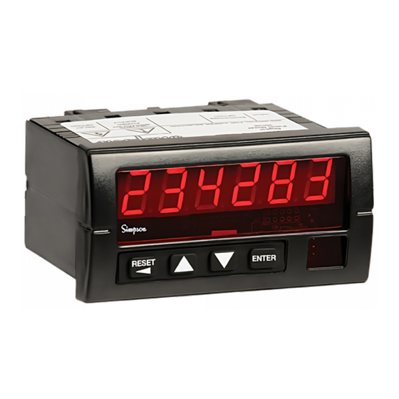
1 Product Description 1.1 General Description The S662 preset totalizer & batch counter fits a 1/8 DIN standard cutout and is perfect for tight spaces, extending only 3.24” (82mm) behind the panel. The unit is UL listed. The unit is for indoor use at altitudes up to 2000m, temperatures between 0° and 40°C, and installation category III, pollution degree 2. -
Page 5: Option Module Summary
Output Supply Figure 1. Option Module Slots (Rear View) The S662 is modular product which uses field configuring slide-in modules. The mod- ules slide easily into the rear of the counter. Table 1 describes available option modules for the S662. -
Page 6: Hardware Setup
2 Hardware Setup 2.1 Panel Installation The S662 1/8 DIN counter requires a standard 1/8 DIN panel cutout of 1.77” (45mm) high by 3.62” (92mm) wide. To install the counter into a panel cutout, remove the clips from the side of the counter. Slide the counter through your panel cutout, then slide the mounting clips back on. -
Page 7: Removing / Installing Option Modules
2.2 Removing / Installing Option Modules Shut power off before removing or installing any option modules Couper le courant avant de retirer ou d’installer des modules optionnels 1. Remove module from case by inserting a screwdriver into tab slot opening at top of input module. -
Page 8: 120/240 Vac Power Module
Coupez l’alimentation avant de raccorder les modules optionnels. Denotes modules position 4 at rear of counter The AC power module allows the S662 to be operated from standard 50/60 Hz line power. The power module will be configured as 120... - Page 9 If channel B is not used, default settings for switch positions 1 through 3 should be se- lected. Default settings are provided in Table 2. The input module also provides for a user input signal. On the S662, this input serves as the secondary channel (Batch) hard-wired reset. This may be used to reset the batch count while preserving the primary count.
-
Page 10: Quadrature Input Module
Table 2. Standard Input Module DIP Switch Settings(* = Factory Default Setting) 1 B Channel Bias: OFF = Hi* VLT = 5.0 V VUT = 7.0V (+/- 10%) ON = Low VLT = 1.6 V VUT = 3.6V (+/- 10%) 2 B Channel Frequency: OFF = Hi* (low pass filter disabled) - Page 11 A, B, and User input signals. The Input module also provides for a User input signal. On the S662, this input serves as the secondary channel (Batch) hard-wired reset. This may be used, for example, to reset the batch count while preserving the primary count.
- Page 12 Table 3. Quadrature Module DIP Switch and Jumper Settings JP1/2: Count Mode Selector Jumpered 1-2 = Quadrature mode Jumpered 2-3 = Standard counter mode SW1: 10 Position DIP Switch * = Factory Default setting 1 B Channel Bias: OFF = Hi* VLT = 5.0V VUT = 7.0V (+/- 10%) ON = Low VLT = 1.6V VUT = 3.6V (+/- 10%)
-
Page 13: Excitation Module
2.6 Excitation Module PHASE A-WHITE A INPUT PHASE B-GREEN COMMON QUADRATURE ENCODER USER INPUT B INPUT ISO+12V COMMON ISOCOM COMMON (BLACK) EXCITATION INPUT QUADRATURE EXCITATION INPUT CARD CARD POSITIVE-RED Figure 11. Wiring Encoder w/ Excitation Supply 12 VDC Excitation Module The Excitation Module can supply 12 VDC at up to 100 mA for external sensors or en- coders. -
Page 14: Single And Dual Relay Modules
Denotes module position 2 at rear of counter ISO+12V 12 VDC, 100 mA max ISOCOM EXCITATION Figure 12. Excitation Module 2.7 Single and Dual Relay Modules Figure 14. Single Relay Figure 15. Dual Relay The Single and Dual Relay modules can activate circuit loads of up to 5 amps at 250 VAC. -
Page 15: Display & Keypad Controls
3 Display & Keypad Controls 3.1 Display Numeric & Message Display Output Status Indicators Units Window 4 Button Keypad Figure 16. Display and Keypad Layout • 6-Digit 0.56” high red LED Display. • 2 Output Status Indicators; “1” and “2.” •... -
Page 16: Display Error Messages
3.2 Display Error Messages Table 4. Display Error Messages Display Description Action Required Cycle power to the counter, if the error The Keypad is disabled or a key is stuck in remains, return PAdErr the ON position counter to factory for repair. -
Page 17: What The Keys Do In The Programming Mode
Display Mode Figure 17. Programming Menu Structure In the Programming Mode, the S662 will return to Display Mode automatically if a key is not pressed within 120 seconds (2 minutes). The menu is comprised of three levels: Setup Menu, Function View and Option Edit. Figure 17 illustrates the three levels of the menu system. -
Page 18: Special Start-Up Modes
3.5 Special Start-Up Modes There are two start-up modes for the S662 counter. The default start-up mode will be used every time the counter is powered up by the user. There is one alternate start-up mode that will allow the operator to return the counter software functions to factory de- fault settings. -
Page 19: Counter Operations And Parameters
This section details the initial programming options of the S662, presuming all defaults are in place. If you are already familiar with the S662 programming, see Appendix B for the Program- ming Quick Reference Guide. To enter the Programming Mode, hold and press p . -
Page 20: A/B Channel Options
If a password is already in the counter, the display will flash between pass, for “En- ter Password,” and the default value, 000. When the display shows 000, press . Use the arrow keys to change the flashing ENTER digit to the desired number. Press to advance to the next digit. -
Page 21: Count 1 Scaling And Display
4.3 Count 1 Scaling and Display (Count 1 Setup) Scale The S662 counter allows for scaling of display values. Scaling allows the counter to dis- play a more accurate number than its 6-digit capacity might otherwise allow. Generally speaking, the smaller the scale value, the more accurate the count will be. The S662 has four prescale values, 1.0 (default), 0.1, 0.01, and 0.001. -
Page 22: Count 2 (Batch) Scaling And Display
The Count 2 display value is independent of the Count 1 display value. The secondary “channel” in the S662 has its own scaling values and decimal position. The Scale 2 mul- tiplier and Decimal Point 2 locations operate similar to that for Count 1. In addition, a Count 2 Prescale is available. - Page 23 Prescale. Prescale The S662 counter allows for prescaling of display values. Prescaling allows the counter to display a more accurate number than its 6-digit capacity might otherwise allow. Gen- erally speaking, the smaller the scale value, the more accurate the count will be. The S662 has four prescale values, 1.0 (default), 0.1, 0.01, and 0.001.
-
Page 24: Output Control Modes
4.5 Output Control Modes (Output Setup) The S662 supports two independent output channels with four modes of operation: disabled, timed, latched and boundary. Output Type Description Disabled Output The output channel is inactive. The timed mode activates an output when a set point or ‘trigger’... -
Page 25: Set Point Parameters
4.6 Set Point Parameters (Set Point Setup) The S662 has four set point parameters and a special value referred to as Reset Position. The Reset Position can be referred to as Count Reset Value. SP1 and SP2 are used only with Output 1, and SP3 and SP4 are used only with Output 2. -
Page 26: Auto Reset Operations
Auto Reset Mode (Reset Setup). 4.7 Auto Reset Operations (Reset Setup) The S662 has the capability to perform a Count Reset event based upon various condi- tions. When Auto Reset occurs, the outputs will return to the deactivated status and the displayed count will return to the value stored in the Reset Position (rstpos) function. -
Page 27: Miscellaneous Controls
Mode Description Only a front panel or external reset event will di SAbL reset count. When the selected set point is encountered, reset At SP# event occurs. Auto Reset occurs after Output 1 times-out AFtoP1 (Output 1 must be in timed mode). Auto Reset occurs after Output 2 times-out AFtoP2 (Output 2 must be in timed mode). -
Page 28: Appendix A: Technical Specifications
ENTER lected. The display will now show end. If you are finished programming the S662, press ENTER If not, use the arrow keys to back up to the necessary parameter. Appendix A: Technical Specifications A.1 Functional Specifications... -
Page 29: Electrical, Environmental And Mechanical Specifications
A.2 Electrical, Environmental and Mechanical Power AC Supply: 120 or 240 VAC, ±10% Requirements Power Consumption Reset Input Signal Active Low: 0.2 VDC = active Storage -10 to 60°C Temperature Operating 0 to 40°C Temperature 0 to 80% for temperatures less than 32°C, Relative Humidity decreasing linearly to 50% at 40°C. - Page 30 Standard input module A, B and User Input Channels High to low transition (A and B channels) Count edge Switch contact, CMOS or TTL logics, PNP or NPN Input Sources devices Sinking: 10K, 5% Res. Pull-up to (9.0 - 16 VDC) ±10% Input Impedance Sourcing: 5.1K, 5% Res.
-
Page 31: Appendix B: Programming Quick Reference
1500 V Appendix B: Programming Quick Reference If you are unfamiliar with navigating menus in the S662, see section 3. Each pa- rameter is listed in the order of appearance in the menu system. Refer to the para- graph indicated in the Tech Note column for technical details on a particular param- eter. - Page 32 Menu Parameter Choices / Description Tech- Category Name Format Note Chan A Mode i nPut A CHAn Select count mode of A SEtuP doW n channel. quad r quad Chan B Mode b CHAn di r* Select count mode for B channel.
- Page 33 Menu Parameter Choices / Description Tech Category Name Format Note Batch Mode Count 2 M m odE duAL* Display value 2 (Count SEtuP bAtCH 2) mode. Defines the counting mode for batch count. Count 2 Prescale PrESCL 1.0* Set prescaling multiplier for Display Value 2.
- Page 34 Menu Parameter Choices / Description Tech Category Name Format Note Output 1 Mode oPut 1 M m odE1 di SAbLE Set the mode of SEtuP ti M m Ed operation for Output 1. LAtCH* Can be disabled, timed, bound latched or boundary mode.
- Page 35 Menu Parameter Choices / Description Tech Category Name Format Note —>At SP1 Output 1 Bindings ti M m Ed<— —>AtSP1* Reminder message LAtCHED<— —>SP2=Hi indicates which and how SP1=Lo <— the set points are used for comparison. Which message is displayed depends on the Output 1 Mode or Source selected.
- Page 36 Menu Parameter Choices / Description Tech Category Name Format Note Output 2 Source SrC 2 Count1* Select which Display Count2 value to be used for Output 2 comparisons / matchpoints. See also SP3 and SP4. Output 2 Batch Reset bAtrSt When output activates, perform Count 2 Reset as well.
- Page 37 Menu Parameter Choices / Description Tech Category Name Format Note 000020* Set point #1 High. Values:-99999 to 999999. Decimal point will appear according to the current Output 1 Source setting. 000030* Set point #2 Low. Values: -99999 to 999999. Decimal point will appear according to the current Output 2 Source setting.
- Page 38 Menu Parameter Choices / Description Tech Category Name Format Note Delay 2 dELAY 010.00* Output 2 delay time. Appears only if Output 2 mode set to timed. Until 2 unti L2 Reset* Output 2 latched until parameter. Appears only if M m ode2 = latch and SRC2 = Count1.
- Page 39 Menu Parameter Choices / Description Tech Category Name Format Note Auto Reset Mode rESEt ArESEt di SAbLE* Selects when an auto SEtuP At SP1 reset function is to occur. At SP2 Disabled, at a setpoint or At SP3 after output times out. At SP4 See also the RSTP1 AFtoP1...
Need help?
Do you have a question about the S662 and is the answer not in the manual?
Questions and answers