
Related Manuals for Simpson S664


Summary of Contents for Simpson S664
- Page 1 S664 Frequency Counter Operation Manual 1.800.561.8187 information@itm.com www. .com...
- Page 2 SIMPSON ELECTRIC COMPANY neither assumes nor authorizes any other persons to assume for it any other liability in connection with the sales of its products.
-
Page 3: Table Of Contents
Contents 1 Product Description......... .3 General Description. -
Page 4: Product Description
1 Product Description General Description The S664 frequency counter fits a 1/8 DIN standard cutout and is perfect for tight spaces, extending only 3.24” (82mm) behind the panel. The unit is UL listed. The unit is for indoor use at altitudes up to 2000m, tem- peratures between 0°... -
Page 5: Part Number Identification
Supply Figure 1. Option Module Slots (Rear View) The S664 is a modular product that uses field configuring slide-in modules. The modules slide easily into the rear of the counter. Figure 1 displays the functional assignments for each module position. Table 1 describes available option modules for the S664. -
Page 6: Hardware Setup
2 Hardware Setup Panel Installation The S664 1/8 DIN counter requires a standard 1/8 DIN panel cutout of 1.77” (45mm) high by 3.62” (92mm) wide. To install the counter into a panel cutout, remove the clips from the side of the counter. Slide the counter through your panel cutout, then slide the mounting clips back on. -
Page 7: Removing / Installing Option Modules
2.2 Removing / Installing Option Modules Shut power off before removing or installing any option modules Couper le courant avant de retirer ou d’installer des modules optionnels 1. Remove module from case by inserting a screwdriver into tab slot opening at top of input module. -
Page 8: 120/240 Vac Power Module
Coupez l’alimentation avant de raccorder les modules optionnels. Denotes modules position 4 at rear of counter The AC power module allows the S664 to be operated from standard 50/60 Hz line power. The power module will be configured as 120... - Page 9 If channel B is not used, default settings for switch positions 1 through 3 should be selected. Default settings are provided in Table 2. The Input module also provides for a User input signal. On the S664, this input serves as a secondary channel (Rate) hard-wired reset. This may be used, for example, to reset latched alarm outputs that have been assigned to rate.
- Page 10 The S664 can accept inputs from many different sensors. The A and B chan- nels may be configured independently as shown in Table 2. Figures 8 and 8a have examples of some typical sensors and the wiring connections that would be used.
-
Page 11: Quadrature Input Module
LOW BIAS LOW BIAS HIGH BIAS HIGH BIAS HIGH FREQUENCY LOW FREQUENCY HIGH FREQUENCY LOW FREQUENCY SINKING SOURCING SINKING SOURCING NPN SENSOR PNP SENSOR Figure 8. Sensor Connection Examples HIGH BIAS LOW BIAS HIGH FREQUENCY LOW FREQUENCY SOURCING SINKING Figure 8a. Sensor Input Example 2.5 Quadrature Input Module The Quadrature / Universal Input Module has two operational modes: Quadrature mode and Standard mode. - Page 12 The Quadrature mode supports a wide range of encoders including the Simpson SE series. While in Standard mode, this module works similarly to the Standard Input module, with the added capability to selectively invert the A, B, and User input signals.
- Page 13 Table 3. Quadrature Module DIP Switch and Jumper Settings JP1/2: Count Mode Selector Jumpered 1-2 = Quadrature mode Jumpered 2-3 = Standard counter mode SW1: 10 Position DIP Switch * = Factory Default setting B Channel Bias: OFF = Hi* VLT = 5.0V VUT = 7.0V (+/- 10%) ON = Low...
-
Page 14: Excitation Module
Figure 2.6 Excitation Module Figure 11. Wiring Encoder w/Excitaion Supply 12 VDC Excitation Module The Excitation Module can supply 12 VDC at up to 100 mA for external sensors or encoders. This excitation is isolated from the counter internal logic supply. When using sensors or encod ers that do not have a signal return or imply a signal return that is in common with the supply voltage, a common attachment that ties the excitation supply to the logic input common may be required. -
Page 15: Display & Rear Panel Controls
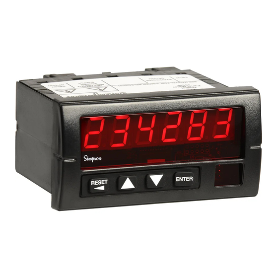
Numeric & Message Display Units Window Figure 14. Display Layout • 6-digit 0.56” high red LED display. • Units Window for supplied label or legend. • Upon power up, the S664 will identify its model and version. 1.800.561.8187 information@itm.com www. .com... -
Page 16: Display Error Messages
Rate (Frequency) Scaling and Display The S664 can measure frequencies ranging from 1.00 Hz to 35 KHz. The fre- quency scale is selected according to Table 4. The frequency range is selected by using a wire or switch across the RESET and COMMON terminals on the rear of the counter. -
Page 17: A/B Channel Inputs
A/B Channel Inputs The A channel input is a pulse source. This signal must be limited to under 35 KHz. This corresponds to a minimum pulse width of 28.57 microseconds. The signal does not need an even duty cycle (On vs. Off time) as long as a minimum (high or low) of 1 microsecond is maintained (See figure 15). -
Page 18: Appendix A: Technical Specifications
Appendix A: Technical Specifications Functional Specifications Frequency modes Scale 1 1.00 to 99.99 Hz 1 update / sec Scale 2 2.0 to 999.99 Hz 1 update / sec Scale 3 4 to 9999 Hz 2 updates / sec Scale 4 0.01 to 35.00 KHz 2 updates / sec Channel A and Channel B... - Page 19 Standard input module Input Channels A, B and User High to low transition (A and B channels) Count edge Switch contact, CMOS or TTL logics, PNP or NPN Input Sources devices Sinking: 10K, 5% Res. Pull-up to (9.0 - 16 VDC) ±10% Input Impedance Sourcing: 5.1K, 5% Res.
Need help?
Do you have a question about the S664 and is the answer not in the manual?
Questions and answers