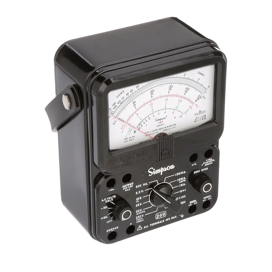
Simpson 260 Instruction Manual
Series 8
volt-ohm-milliammeters
Hide thumbs
Also See for 260:
- Operator's manual (68 pages) ,
- Instruction manual (27 pages) ,
- Operator's manual (45 pages)
Table of Contents
Advertisement
Quick Links
Advertisement
Table of Contents

Related Manuals for Simpson 260


Summary of Contents for Simpson 260
- Page 1 Simpson 260 Series 8 ® Volt-Ohm-Milliammeters INSTRUCTION MANUAL...
- Page 2 This warranty shall not apply to any instrument or other article of equipment which shall have been repaired or altered outside the SIMPSON ELECTRIC COMPANY factory or authorized service centers, nor which has been subject to misuse, neg- ligence or accident, incorrect wiring by others, or installation or use not in accord with instructions furnished by the manufacturer.
- Page 3 NOTES...
-
Page 4: Table Of Contents
Contents 1 INTRODUCTION ................. 6 1.1 General Description ................6 1.2 Overload Protection ................6 1.3 Internal Batteries .................. 7 1.4 Printed Circuit ..................7 1.5 Phenolic Case ..................7 1.6 Adjust-A-Vue Case ................7 1.7 Test Leads ..................... 7 1.8 Technical Data .................. - Page 5 OPERATOR MAINTENANCE ............27 5.1 General ....................27 5.2 Inspection .................... 27 5.3 Battery Replacement ................28 5.4 Fuse Replacement ................28 5.5 Test Lead Inspection ................28 5.6 Care ...................... 29...
-
Page 6: Introduction
Mirrored Dial Overload Protection No single protective device nor even a combination of devices as found in the 260 can fully protect a multi-purpose Instrument under all overload conditions. Over- loads of such severity as to damage the Instrument despite all the built-in protec- tion provided are possible when the Instrument is misused. -
Page 7: Internal Batteries
Rubber plug bumpers on the bottom of the case reduce sliding should the 260 be accidentally pulled by the test leads when the Instrument is on a workbench. -
Page 8: Technical Data
Frequency Response: Referenced to 100 Hz (Figures 4-4 and 4-9) Resistance Ranges: R X 1: 2.5° of Arc R X 100: 2° of Arc R X 10,000: 2° of Arc Accuracies specified are for the 260 in a horizontal position. -
Page 9: Definition Of Accuracy
10. DECIBELS: Range: –20 to +10 dB, –8 to +22 dB, 0 to +30 dB, +6 to +36 dB, +20 to +50 dB Reference Level: With zero dB power level equal to 1 mW across a 600V line. 11. BATTERIES: Voltage: 1.5V, 9V NEDA No.:... - Page 10 The 10,000 V AC accessory probe is similar to the high voltage DC probes with the following exceptions: The AC high voltage probe is designed to extend the 260-8 AC voltage range. The probe can be used with the Simpson 260-8 10-volt AC range.
- Page 11 260-8 as an AC voltage. The Amp-Clamp has a range selector with 6 positions. Any of the following cur- rent ranges can be used with the 260-8: 5, 10, 25, 50, 100 or 250 amperes. NOTE: Instructions are furnished with each Amp-Clamp.
-
Page 12: Installation
Warranty The Simpson Electric Company warranty policy is printed in the front of this manual. Read it carefully prior to requesting any warranty repairs. For assistance of any kind, including help with the Instrument under warranty, contact the nearest Au- thorized Service Center for instructions. -
Page 13: Controls, Jacks And Indicators
3 CONTROLS, JACKS AND INDICATORS General The functions of all the controls, jacks and indicators used to operate the Simpson 260-8 are described in this section. Become familiar with each item prior to oper- ating the Instrument. Front Panel Description Figure 3-1 depicts the front panel controls, jacks and indicators described below. -
Page 14: Operation
The 260-8 should only be used by personnel qualified to recognize shock hazards and trained in the safety precautions required to avoid possible in- jury. -
Page 15: Polarity Reversing
ments. A mistake could result in damage to the Instrument and possible personal injury. Locate all voltage sources and accessible current paths before making con- nections to circuitry. High voltage may appear unexpectedly or in unexpected locations in faulty equipment. An open bleeder resistor, for example, may result in a capacitor retaining a dangerous charge. -
Page 16: Dc Voltage Measurement 0-250Mv Range
DC Voltage Measurement 0-250mV Range Prior to making voltage measurements, review the SAFETY PRE- CAUTIONS listed in paragraph 4.2. Also, when using the 260 as a millivoltmeter, care must be taken to prevent damage to the indicat- ing instrument from excessive voltage. Before using the 250 millivolt range, use the 1.0-volt DC range to determine that the voltage mea-... -
Page 17: Dc Voltage Measurement 0-2.5 ~ 0-250V Range
DC Voltage Measurement 0-2.5 ~ 0-250V Range Set the function switch at +DC (Figure 4-1). Plug the black test lead into the – COMMON jack and the red test lead into the + jack. Set the range switch at one of the five voltage range positions marked 2.5V, 10V, 25V, 50V or 250V. -
Page 18: Dc Voltage Measurement 0-1000V Range
4.10 DC Voltage Measurement 0-1000V Range Be extremely careful when working with high voltage circuits. Do not touch the Instrument or test leads while power is on in the circuit being measured. Before proceeding with the following steps, review the Safety Precautions in 4.2. a. -
Page 19: Ac Voltage Measurement 0-2.5 ~ 0-250V Range
The 260 responds to the average value of an AC waveform. It is calibrated in terms of the RMS value of a pure sine wave. If the waveform is nonsinusoidal, and depending upon its waveform, the reading may be either higher or lower than the true RMS value of the measured voltage. -
Page 20: Ac Voltage Measurement 0-500V Range
Plug the black test lead into the – COMMON jack and the red test lead into the + jack. Turn off power to the circuit to be measured and discharge any capacitors. Connect the test leads across the circuit voltage to be measured with the black lead to the grounded side. -
Page 21: Ac Voltage Measurement 0-1000V Range
4.13 AC Voltage Measurement 0-1000V Range Be extremely careful when working in high voltage circuits. Do not handle the Instrument or test leads while the circuit being measured is energized. OBSERVE ALL SAFETY PRECAUTIONS in paragraph 4.2 and in the instruction manual for the equipment being tested. Do not attempt any voltage measurement which may exceed 1000 volts or the circuit-to-ground voltage of the Instrument, 1000 volts maximum. -
Page 22: Output Voltage Measurement
AC and DC voltage levels exist. This occurs primarily in amplifier circuits. The 260-8 has a 0.1 mfd, 400 volt capacitor in series with the OUTPUT jack. The capacitor blocks the DC component of the current in the test circuit, but allows the AC or desired component to pass on to the indicating instrument circuit. -
Page 23: Decibel Measurement (-20 To +50 Db)
In some industries, measurements are made in terms of voltage or current ratios (decibels) based on a specific reference level. The dB scale on the 260-8 serves this purpose and is calibrated to a reference level (zero dB) of 0.001 watt into 600 ohms. -
Page 24: Direct Current Measurement 0-50Μa Range
4.17 Direct Current Measurement 0-50μA Range Set the function switch at +DC. Plug the black test lead into the –COMMON jack and the red test lead into the +50μAMPS/250mV jack. Set the range switch at 50μAMPS (dual position with 50V). Open the ground side of the circuit in which the current is being measured. -
Page 25: Resistance Measurements
0-10 figures to read directly in amperes. Turn the power off and disconnect the test leads. The 10A range is not internally fused in the 260-8. When using the 10A range, never disconnect a test lead from a jack or from the circuit while the circuit is energized. Doing so may likely damage the test jacks or leads and the arcing may be hazardous to the operator. -
Page 26: Measuring Resistance
4.21 Measuring Resistance Before measuring resistance in a circuit, make sure the power is off to the circuit being tested and all capacitors are discharged. Disconnect shunting components from the circuit before measuring its resistance. Set the range switch to one of the resistance range positions as follows (Fig- ure 4-12): Use R X 1 for resistance readings from 0 to 200 ohms. -
Page 27: Operator Maintenance
260-8. Inspection The user is protected from electrical shock by the insulation of the 260 and its test leads. Frequently examine them for any insulation damage such as cracks, cuts, chips, burns or deterioration that ex-... -
Page 28: Battery Replacement
Battery Replacement Two batteries are used inside the case to supply power for resistance mea- surements. One is a 1.5-volt D cell and the other is a 9-volt battery. When it is no longer possible to adjust the pointer to zero for the R X 1 and R X 100 ranges (refer to ZERO OHMS ADJUSTMENT paragraph 4.20), replace the 1.5-volt cell. -
Page 29: Care
Care Immediately clean all spilled materials from the Instrument and wipe dry. If the spillage is corrosive, use a suitable cleaner to neutralize the corrosive action. Whenever the Instrument is not in use, rotate the function switch to the OFF posi- tion. - Page 30 NOTES...
- Page 31 NOTES...
- Page 32 SIMPSON ELECTRIC COMPANY 520 Simpson Avenue Lac du Flambeau, WI 54538-0099 (715) 588-3311 FAX (715) 588-3326 Printed in U.S.A. Part No. 06-114338 Edition 12, 06/17 Visit us on the web at: www.simpsonelectric.com...
Need help?
Do you have a question about the 260 and is the answer not in the manual?
Questions and answers