Table of Contents
Advertisement
Advertisement
Table of Contents

Related Manuals for Simpson 260 Series 8


Summary of Contents for Simpson 260 Series 8
- Page 1 ® Simpson 260 Series 8 Volt-Ohm-Milliammeters INSTRUCTION MANUAL...
- Page 2 SIMPSON ELECTRIC COMPANY neither assumes nor autho- rizes any other persons to assume for it any other liability in connection with the sales of its products.
- Page 3 NOTES...
-
Page 4: Table Of Contents
Contents 1. INTRODUCTION ................. 7 General Description ................7 Overload Protection ................7 Internal Batteries ................7 Printed Circuit ..................8 Phenolic Case ..................8 Adjust-A-Vue Handle ................8 Test Leads ..................8 Technical Data ..................8 Definition of Accuracy ............... 10 1.10 Safety Considerations .............. - Page 5 NOTES...
- Page 6 NOTES...
-
Page 7: Introduction
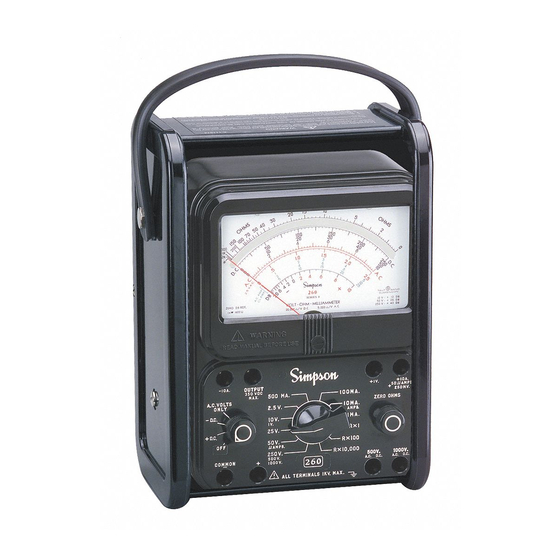
1. INTRODUCTION General Description The Simpson Volt-Ohm-Milliammeter 260 Series 8, (hereafter referred to as the 260 or as the Instrument) is a rugged, accurate, compact, easy-to-use Instrument equipped with mirrored dial to eliminate parallax. The Instrument can be used to make accurate measurements of AC and DC voltage, direct current, resistance, decibels, and Output Voltage. -
Page 8: Printed Circuit
Printed Circuit Most of the component parts are mounted on a printed circuit board which simpli- fies assembly and maintenance, thus, extending the useful life of the Instrument. Phenolic Case The phenolic case has heavy reinforced walls for maximum durability and pro- vides excellent protection for the circuit components. - Page 9 DC MICROAMPERES: Range: 0-50µA Voltage Drop: 250mV DC MILLIAMPERES: Ranges: 0-1-10-100-500 mA Voltage Drop (Approx.): 250 mV, 255 mV, 300 mV, 500 mV DC AMPERES: Range: 0-10A Voltage Drop (Approx.): 255 mV NOTE: The 10A range is not internally fused. µ...
-
Page 10: Definition Of Accuracy
15. WEIGHT: 3 lbs. (1.359 kg) 16. ***RATED-CIRCUIT-TO- GROUND VOLTAGE: 1000V AC/DC Max. ***Per ANSI C 39.5 April 1974: “The specified voltage with respect to ground, which may be safely and continuously applied to the circuit of an Instrument.” Definition of Accuracy The voltage and current accuracy of this Instrument is commonly expressed as a percent of full scale. -
Page 11: Accessory Ac High Voltage Probe
Warranty The Simpson Electric Company warranty policy is printed on the inside front cover of this manual. Read it carefully before requesting any warranty repairs. For all assistance, including help with the Instrument under warranty, contact the nearest Authorized Service Center. -
Page 12: Power Source Requirements
Instrument is calibrated in this position. 3. CONTROLS, JACKS AND INDICATORS The functions of all the controls, jacks and indicators used to operate the Simpson 260-8 are described in this section. Become familiar with each item before oper- ating the Instrument. - Page 13 -10 A. +10A OUTPUT +1V. AMPS. 350 VDC 500 MA. 100MA. A.C. VOLTS 250 MV. MAX. ONLY 2.5 V. 10MA. ZERO OHMS AMPS. - D.C. 10 V. 1MA. 25 V. R x 1 + D.C. 50 A. R X I00 AMPS.
-
Page 14: Operation
4. OPERATION Multifunction instruments (VOM’s) such as the 260-8 are intended as general purpose measuring Instruments for use in low power circuitry such as found in consumer appliances, TV and radio receivers, and in general laboratory applica- tions. Their use is not recommended in high voltage, high power circuitry where operator errors and inadequate personal protective measures could result in serious injury from arcing or explosion. -
Page 15: Polarity Reversing
Locate all voltage sources and accessible current paths before making con- nections to circuitry. High voltage may appear unexpectedly or in unexpected locations in faulty equipment. An open bleeder resistor, for example, may result in a capacitor retaining a dangerous charge. Make certain that the equipment being worked on is properly grounded and fuses are the proper type and rating. -
Page 16: Dc Voltage Measurement 0-250Mv Range
DC Voltage Measurement 0-250mV Range Before making voltage measurements, review the SAFETY PRECAUTIONS listed in paragraph 4.1. Also, when using the 260 as a millivoltmeter, care must be taken to prevent damage to the indicating instrument from excessive voltage. Before using the 250 millivolt range, use the 1.0-volt DC range to determine that the voltage measured is not greater than 250 millivolts (or .25 volt DC). -
Page 17: Dc Voltage Measurement 0-2.5 ~ 0-250V Range
DC Voltage Measurement 0-2.5 ~ 0-250V Range Set the function switch at +DC (Figure 4-1). Plug the black test lead into the – COMMON jack and the red test lead into the + jack. Set the range switch at one of the five voltage range positions marked 2.5V, 10V, 25V, 50V or 250V. -
Page 18: Dc Voltage Measurement 0-1000V Range
DC Voltage Measurement 0-1000V Range Use extreme care when working with high voltage circuits. Do not touch the Instrument or test leads while power is on in the circuit being measured. Before proceeding with the following steps, review the Safety Precautions in paragraph 4.1. -
Page 19: Ac Voltage Measurement 0-500V Range
Before proceeding with the following steps, review the Safety Precautions in Paragraph 4.1. Set the function switch to AC Volts Only position (Figure 4- AC VOLTAGE RANGES 2.5 VAC RANGE 10 VAC RANGE NOTE: The meter will not indicate if 25 VAC RANGE 50 VAC RANGE the switch is incorrectly set to a DC... -
Page 20: Ac Voltage Measurement 0-1000V Range
Do not attempt any voltage measurement which may exceed 1000 volts or the circuit-to-ground voltage of the Instrument, 1000 volts maximum. Be sure that the range switch is set to the 250V/500V/1000V range, function switch to AC volts only position, and test leads connected to common and 500V jack. -
Page 21: Output Voltage Measurement
jack. Do not touch the Instrument or test leads while the power is on in the circuit being measured. Before proceeding with the fol- lowing steps, review the Safety Precautions in Paragraph 4.1. Set the function switch at AC (Figure 4-7). Set the range switch at 250V/500V/1000V position. -
Page 22: Decibel Measurement (-20 To +50 Db)
Before proceeding with the fol- lowing steps, review the Safety Precautions in Paragraph 4.1. Set the function switch to AC volts only position (Fig- ure 4-9). Plug the black test lead into the -COMMON jack and the red test lead into the OUT- PUT jack. -
Page 23: Direct Current Measurement
Use operating instructions for AC VOLTAGE MEASUREMENT, 0-2.5/10/25/ 50/250V RANGES (paragraph 4.10). NOTE: Do not use the 500V or 1000V ranges for decibel readings. Read decibels on the bottom scale marked dB. For the 10/25/50/250V ranges, add the appropriate factor from the chart below: NOTE: The maximum voltage ratio that can be measured is +50 dB on the 0- 250V range. -
Page 24: Direct Current Measurement 0-1Ma Through 0-500Ma Range
4.15.2 Direct Current Measurement 0-1mA through 0-500mA Range Set the function switch at +DC (Figure 4-11). Plug the black test lead into the – COMMON jack and the red test lead into the + jack. Set the range switch at one of the four range positions marked 1 mA, 10 mA, 100 mA or 500 mA. -
Page 25: Resistance Measurements
Turn the power off and disconnect the test leads. NOTE: The 10A range is not internally fused in the 260-8. When using the 10A range, never disconnect a test lead from a jack or from the circuit while the circuit is energized. Doing so may damage the test jacks or leads and the arcing may be hazardous to the operator. -
Page 26: Resistance Measurement Of Semiconductors
Observe the reading on the OHMS scale at the top of the dial. NOTE: The OHMS scale reads from right to left for increasing values of resistance. To determine the actual re- sistance value, multiply the reading by the factor at the switch position. -
Page 27: Operator Maintenance
OPERATOR MAINTENANCE The following paragraphs in this section describe battery replacement, fuse re- placement, and preventive maintenance procedures for the 260-8. Inspection The user is protected from electrical shock by the insulation of the 260 and its test leads. Frequently examine them for any insulation damage such as cracks, cuts, chips, burns or deterioration that expose internal metal parts or reduce the spac- ing between such metal parts and hand contact by the operator. -
Page 28: Fuse Replacement
NOTE: Batteries should be replaced before their useful life has expired. Failure to do so may result in corrosion and battery leakage. Observe polarity when replacing the 1.5-volt D cell and connect as indicated. The D cell is held in place with spring clips which also act as battery contact clips. - Page 29 NOTES...
- Page 30 NOTES...
- Page 31 NOTES...
- Page 32 SIMPSON ELECTRIC COMPANY 853 Dundee Avenue Elgin, IL 60120-3090 (847) 697-2260 FAX (847) 697-2272 Printed in U.S.A. Part No. 06-114338 Edition 10, 1/02 Visit us on the web at: www.simpsonelectric.com...
Need help?
Do you have a question about the 260 Series 8 and is the answer not in the manual?
Questions and answers