
Subscribe to Our Youtube Channel
Related Manuals for Simpson 260-8PRT


Summary of Contents for Simpson 260-8PRT
- Page 1 Simpson 260 Series 8P ® Volt-Ohm-Milliammeters INSTRUCTION MANUAL 1.888.610.7664 www.calcert.com sales@calcert.com...
- Page 2 This warranty shall not apply to any instrument or other article of equipment which shall have been repaired or altered outside the SIMPSON ELECTRIC COMPANY factory or authorized service centers, nor which has been subject to misuse, neg- ligence or accident, incorrect wiring by others, or installation or use not in accord with instructions furnished by the manufacturer.
-
Page 3: Table Of Contents
Contents 1. INTRODUCTION ................6 General Description ................6 Overload Protection ................6 Internal Batteries ................7 Overload Circuit Test ................7 Printed Circuit ..................8 Phenolic Case ..................8 Adjust-A-Vue Handle ................8 Test Leads ..................8 Technical Data ..................8 1.10 Definition of Accuracy ............... - Page 4 Battery Replacement ................27 Fuse Replacement ................27 Test Lead Inspection ................28 Care ....................28 1.888.610.7664 www.calcert.com sales@calcert.com...
-
Page 5: Introduction
INTRODUCTION General Description The Simpson Volt-Ohm-Milliammeter 260 Series 8P, (hereafter referred to as the 260 or as the Instrument) is a rugged, accurate, compact, easy-to-use Instrument equipped with mirrored dial to eliminate parallax. The Instrument can be used to make accurate measurements of AC and DC voltage, direct current, resistance, decibels, and Output Voltage. -
Page 6: Internal Batteries
tacts. Some overload conditions may cause the fuses to burn out as well as open the relay contacts. d. When an overload of sufficient magnitude is applied to the VOM, the reset button will “pop-up” approximately 3/16" above the surface of the panel. To reset the VOM for normal operation, first remove the overload and depress the button. -
Page 7: Printed Circuit
Printed Circuit Most of the component parts are mounted on a printed circuit board which simpli- fies assembly and maintenance, thus, extending the useful life of the Instrument. Phenolic Case The phenolic case is designed with heavy reinforced walls for maximum durabil- ity and provides excellent protection for the circuit components. - Page 8 DC MICROAMPERES: Range: 0-50μA Voltage Drop: 250mV DC MILLIAMPERES: Ranges: 0-1-10-100-500 mA Voltage Drop (Approx.): 250 mV, 255 mV, 300 mV, 500 mV DC AMPERES: Range: 0-10A Voltage Drop (Approx.): 255mV NOTE: The 10A range is not internally fused. μ *ACCURACY: DC Voltage Ranges: 2% of Full Scale...
-
Page 9: Definition Of Accuracy
*Accuracies specified are for the 260 in a horizontal position. **Responds to the average value of an AC current, and is calibrated to indicate the RMS value of a pure sine wave. ***Per ANSI C39.5 April 1974: “The specified voltage with respect to ground, which may be safely and continuously applied to the circuit of an Instrument.”... -
Page 10: Accessory Ac High Voltage Probe
The 10,000 volts AC accessory probe is similar to the high voltage DC probes with the following exceptions: The AC high voltage probe is designed to extend the 260-8P AC voltage range. The probe can be used with the Simpson 260-8P 10-volt AC range. -
Page 11: Shipping
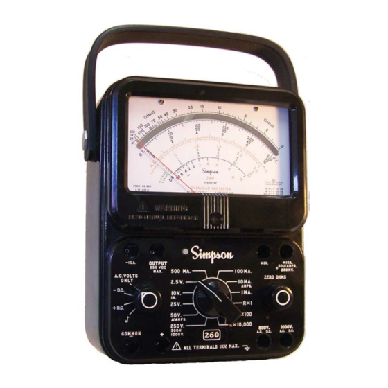
3. CONTROLS, JACKS, AND INDICATORS All operating and adjustment controls, jacks, and indicators for the Simpson 260- 8P are illustrated in this section along with a list (Table 3-1) describing their function. Become familiar with each item before operating the Instrument. - Page 12 -10 A. OUTPUT +10A +1V. AMPS. 350 VDC 500 MA. 100MA. A.C. VOLTS 250 MV. MAX. ONLY 2.5 V. 10MA. ZERO OHMS AMPS. - D.C. 10 V. 1MA. 25 V. R x 1 + D.C. 50 A. R X I00 AMPS.
-
Page 13: Operation
set on the zero mark, reverse the direction of rotation of the zero adjuster slightly to introduce mechanical freedom or “play”, but insufficient to disturb the position of the indicat- ing pointer. This procedure will avoid disturbances to the zero setting by subsequent changes in temperature, hu- midity, vibration, and other environmental conditions. -
Page 14: Polarity Reversing
Do not work alone on high voltage circuits. Make certain that someone ca- pable of giving aid is nearby and alert. Do not handle the Instrument, its test leads, or the circuitry while high voltage is being applied. Hands, shoes, floor, and workbench must be dry. Avoid making measure- ments under humid, damp, or other environmental conditions that could effect the dielectric withstanding voltage of the test leads or Instruments. -
Page 15: Test Leads
Test Leads Test leads are provided with accessory screw-on alligator clips which may be attached to the probe tips. Eliminating the need to hand-hold test prods to a circuit for extended periods, the test clips also reduce hand proximity to a high voltage circuit while energized. -
Page 16: Dc Voltage Measurement 0-2.5 Through 0-250V Range
4.5.3 DC Voltage Measurement 0-2.5 Through 0-250V Range Set the function switch at +DC (Figure 4-2). Plug the black test lead into the -COM- MON jack and the red test lead into the + jack. Set the range switch at one of the five voltage range positions marked 2.5V, 10V, 25V, 50V or 250V. -
Page 17: Dc Voltage Measurement 0-1000V Range
charged. Connect the black test lead to the negative side of the circuit being measured and the red test lead to the positive side of the circuit. Turn on power in circuit being measured. Read the voltage using the 0-50 figures on the black scale marked DC. Multiple the reading by 10. -
Page 18: Ac Voltage Measurement 0-2.5 Thru 0-250V Range
depending upon its waveform, the reading may be higher or lower than the true RMS value of the measured voltage. Thus an error may be introduced if the 260 is used to measure a nonsinusoidal waveform. Also, accuracy is lessened at higher input frequencies (Figure 4-5). -
Page 19: Ac Voltage Measurement 0-500V Range
4.6.2 AC Voltage Measurement 0-500V Range Do not attempt any voltage measurement which may exceed 1000 volts or the circuit-to-ground voltage of the Instrument, 1000 volts maximum. Be sure that the range switch is set to the 250V/500V/1000V range, function switch to AC Volts Only position, and test leads connected to common and 500V jack. -
Page 20: Output Voltage Measurement
Be sure that the range switch is set to the 250V/500V/1000V range, function switch to AC position, and test leads connected to common and 1000V jack. Do not touch the Instrument or test leads while the power is on in the circuit being measured. -
Page 21: Decibel Measurement (-20 To +50 Db)
OUTPUT RANGES 2.5 VAC RANGE 10VAC RANGE 25/50 VAC RANGE 250 VAC RANGE OUTPUT 350 VDC 500 MA. A.C. VOLTS MAX. ONLY 2.5 V. 10 V. 25 V. 50 A. AMPS. 250 V. 500 V. I000 V. COMMON 10Hz 100Hz 1KHz 10KHz 100KHz... -
Page 22: Direct Current Measurement
NOTE: The maximum voltage ratio that can be measured is +50 dB on the 0-250V range. If dB measurements are being made to a 0.006 watt into 500 ohm reference level, subtract +7 dB from the reading obtained on the 260. Direct Current Measurement Do not change the range setting of the range or function switches while... -
Page 23: Direct Current Measurement 0-10A Range
Open the grounded side of the circuit in which the current is being measured. Connect the VOM in series with the circuit. Connect the red test lead to the positive side and the black test lead to the negative side. Turn the power on. -
Page 24: Resistance Measurements
4.10 Resistance Measurements Voltage applied to a resistance range will cause reading errors if low and dam- age the Instrument if high. When making in-circuit measurements, make certain that the circuit is completely de-energized before making connections to it. When making in-circuit measurements, circuit paths in parallel with the resis- tance being measured may cause reading errors. -
Page 25: Continuity Tests
Rotate the function switch between the two DC positions to reverse polarity. This will determine if there is a difference between the resistance in the two directions. To check a semiconductor in or out of a circuit (forward and reverse bias resistance measurements) consider the following be- fore making the measurement: The polarity of the internal ohmmeter... -
Page 26: Operator Maintenance
OPERATOR MAINTENANCE The following paragraphs of this section describe battery replacement, fuse re- placement, and preventive maintenance procedures for the 260. Inspection The user is protected from electrical shock by the insulation of the 260 and its test leads. Frequently examine them for any insulation damage such as cracks, cuts, chips, burns or deterioration that expose internal metal parts or reduce the spac- ing between such metal parts and hand contact by the operator. - Page 27 Test Lead Inspection Periodic inspection of the test leads is recommended to detect cuts, burned areas, dete- rioration or other damage that could reduce the insulation strength of leads. Care Immediately clean all spilled materials from the Instrument and wipe dry. If the spillage is corrosive, use a suitable cleaner to neutralize the corrosive action.
Need help?
Do you have a question about the 260-8PRT and is the answer not in the manual?
Questions and answers