Table of Contents
Advertisement
Quick Links
Advertisement
Table of Contents

Related Manuals for Simpson 228


Summary of Contents for Simpson 228
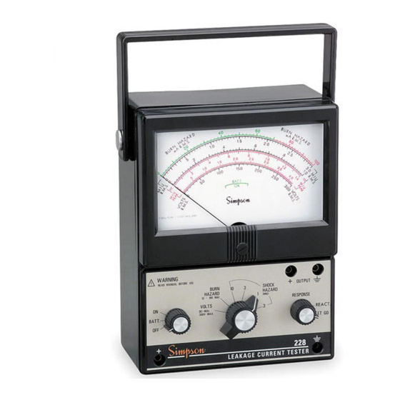
- Page 1 Model 228 Current Leakage Tester INSTRUCTION MANUAL...
- Page 2 SIMPSON ELECTRIC COMPANY neither assumes nor autho- rizes any other persons to assume for it any other liability in connection with the sales of its products.
-
Page 3: Voltage Measurement 1
229-2 uses the measurement networks specified in UL-1244 and is suitable for measuring shock hazard as defined in that document. Instruments such as the Model 228 are intended for use in relatively low power 120/ 240 VAC or dry batter y operated circuits. Never use this Instrument for measure- ments in high-energy or high-power circuitry such as power substations, distribution centers, RF induction heaters, broadcast transmitters and X-ray equipment. -
Page 4: Table Of Contents
Contents 1. INTRODUCTION ................5 1.1 General Description ................5 1.2 What Is Leakage Current? ..............5 1.3 Human Response to Electrical Shock ........... 6 1.4 Shock Hazard ..................7 1.5 Burn Hazard ................... 7 1.6 Inspection of Instrument ................. 7 1.7 Components and Accessories ............... -
Page 5: Introduction
NOTE: For specification information call: ANSI at (212) 642-4900 or UL in Northbrook, IL at (847) 272-8800. The Model 228 tests equipment operating at 120-220 volts AC or DC power line circuits only . Instrument features include: • Separate leakage current networks for measuring the following electrical... -
Page 6: Human Response To Electrical Shock
This high-frequency current may be a significant part of the total leakage current. The human body becomes less sensi- tive to leakage current as the frequency is increased. The 228 takes the frequency of the leakage current into account when making measurements and displays a reading that correctly reflects the potential hazard from the leakage current. -
Page 7: Shock Hazard
When making routine leakage current measurements as part of equipment main- tenance, refer to the equipment manufacturer for the acceptable leakage current level. When using the 228 for testing safety of new designs, check with the appro- priate safety agency for the correct leakage current limits. -
Page 8: Specifications
SPECIFICATIONS *Relative to ANSI C101-1992 or UL-1459 2nd edition Table 1. Specifications Output Sensitivity: Full scale meter deflection equals 1 volt RMS (measured with a 1M , 12 pF load) Voltmeter Range: 0-300 volts (AC or DC) Voltmeter Accuracy: DC to1 Hz: Pointer tracks within 5% of peak 2Hz to 19Hz (Accuracy not supported) -
Page 9: Controls And Functions
Weight: 2½ lbs. (1,134 g) Low-Battery Indication: Instrument provides a battery test selection on power switch and corresponding scale on meter dial. CONTROLS AND FUNCTIONS Meter Dial BATT. Mechanical Zero Adjustment Screw WARNING READ MANUAL BEFORE USE OUTPUT SHOCK HAZARD BURN (MIU) HAZARD... -
Page 10: Interpreting The Meter Dial Scales
Burn Hazard Scale (measured in mA RMS) Used when selecting the BURN HAZARD function in order to read potential burn hazard leakage current. Shock Hazard Scales (measured in MIU RMS and MIU Peak) Used when selecting the SHOCK HAZARD function in order to measure shock hazard leakage current. -
Page 11: Reading The Meter Dial Scales
READING THE METER DIAL SCALES The analog meter scales require interpolation to obtain readings that fall in be- tween the major scale markings. See Figure 3 below, as example. Example: Burn hazard reading is 50mA RMS or MIU (bottom) reading is 1.5 MIU for the 3 MIU range Figure 3 “+”... -
Page 12: Measurement Procedures
(or from the equipment manufacturer) for correct main con- nection, detailed test procedures and leakage current limits. Figure 4, Page 13, shows a typical test setup. All items other than the 228 and its accessories must be provided b y the user. -
Page 13: Preparation
BATT. SW 2 Appliance Under Test 120V WARNING READ MANUAL BEFORE USE OUTPUT SHOCK BURN HAZARD HAZARD (MIU) RESPONSE (0-100µA) Open VOLTS DC-1KHz REACT. 300 Volts max BATT. LET GO Ground LEAKAGE CURRENT TESTER Grounded Supply Connector Figure 4. Typical Test Setup Preparation Turn power OFF to equipment under test. -
Page 14: Burn Hazard Measurement
Turn Function Select switch to VOLTS. Connect Instrument Ground Test Lead to known good ground (such as a water pipe or power line ground). With SW1 open, turn ON equipment under test. Use Positive Test Lead to probe all accessible conductive surfaces to deter mine if excessive voltage is present. -
Page 15: Shock Hazard Measurement
Shock Hazard Measurement Turn Function Select Switch to 10MIU SHOCK HAZARD (see Figure 7 below). WARNING READ MANUAL BEFORE USE OUTPUT SHOCK HAZARD BURN (MIU) RESPONSE HAZARD (0-100mA) REACT. BATT. LET GO LEAKAGE CURRENT TESTER Figure 7 Use Positive Test Lead to probe all accessible conductive surfaces and check for excessive current leakage. -
Page 16: Maintenance And Care
Service The Model 228 Current Leakage Tester contains no operator-serviceable par ts, ex- cept for the batteries and the fuse. Refer all service requests to an authorized service dealer or to the factor y. -
Page 17: Fuse Replacement
Verify Instr ument calibration by performing operational checks using known value sources. For information on Instrument calibration, call Simpson Customer Ser- vice. It is recommended that the Instrument be returned annually to the factory for inspection and calibration. -
Page 18: Rms Vs. Peak
The Instrument provides a peak reading scale on the dial as a convenience for users who have verified that a sinusoidal current is present. The output on the Model 228 provides the user with the ability to measure the waveform that comes out of the measurement network. - Page 19 NOTES...
- Page 20 SIMPSON ELECTRIC COMPANY 853 Dundee Avenue 520 Simpson Avenue, Lac Du Flambeau, WI 54538-0099 Elgin, IL 60120-3090 (847) 697-2260 FAX (847) 697-2272 Printed in U.S.A. Part No. 06-115537 Edition 4, 7/04 Visit us on the w eb at: www.simpsonelectr ic.com...
Need help?
Do you have a question about the 228 and is the answer not in the manual?
Questions and answers