
Related Manuals for Simpson S663


Summary of Contents for Simpson S663
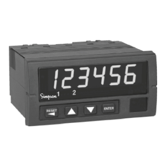
- Page 1 S663 Digital Preset / Totalizer Counter & Rate Meter Operation Manual 1.800.561.8187 information@itm.com www. .com...
- Page 2 SIMPSON ELECTRIC COMPANY neither assumes nor authorizes any other persons to assume for it any other liability in connection with the sales of its products.
-
Page 3: Table Of Contents
Contents 1 Product Description............3 General Description. -
Page 4: Product Description
1 Product Description 1.1 General Description The S663 preset counter and rate meter fits a 1/8 DIN standard cutout and is perfect for tight spaces, extending only 3.24” (82mm) behind the panel. The unit is UL listed. The unit is for indoor use at altitudes up to 2000m, temperatures between 0°... -
Page 5: Part Number Identification
Supply Figure 1. Option Module Slots (Rear View) The S663 is a modular product which uses field configuring slide-in modules. The modules slide easily into the rear of the counter. Figure 1 displays the functional assignments for each module position. -
Page 6: Hardware Setup
2 Hardware Setup 2.1 Panel Installation The S663 1/8 DIN counter requires a standard 1/8 DIN panel cutout of 1.77” (45mm) high by 3.62” (92mm) wide. To install the counter into a panel cutout, remove the clips from the side of the counter. -
Page 7: Removing / Installing Option Modules
2.2 Removing / Installing Option Modules Shut power off before removing or installing any option modules Couper le courant avant de retirer ou d’installer des modules optionnels 1. Remove module from case by inserting a screwdriver into tab slot opening at top of input module. -
Page 8: 120/240 Vac Power Module
Remove power before wiring option modules. Coupez l’alimentation avant de raccorder les modules optionnels. Denotes modules position 4 at rear The AC power module allows the S663 to be of counter operated from standard 50/60 Hz line power. The power module will be configured as 120 VAC or 240 VAC per markings on the back panel. - Page 9 If channel B is not used, default settings for switch positions 1 through 3 should be selected. Default settings are provided in Table 2. The Input module also provides for a User input signal. On the S663, this input serves as a count enable/disable control. Connecting User to Common will disable counting.
-
Page 10: Quadrature Input Module
A, B, and User input signals. The Input module also provides for a User input signal. On the S663, this input serves as a Rate hard-wire reset. This may be used, for example, to reset a latched output configured as an over speed alarm. - Page 11 NOTE: If B channel is not going to be used, use the default switch settings for SW1 positions 1 through 3. Default settings are provided in Table 3. In both modes, the state of the User input signal can be selected as active high or active low.
- Page 12 Table 3. Quadrature Module DIP Switch and Jumper Settings JP1/2: Count Mode Selector Jumpered 1-2 = Quadrature mode Jumpered 2-3 = Standard counter mode SW1: 10 Position DIP Switch *= Factory Default setting 1 B Channel Bias: OFF = Hi* VLT = 5.0V VUT = 7.0V (+/- 10%) ON = Low VLT = 1.6V VUT = 3.6V (+/- 10%) 2 B Channel Frequency:...
-
Page 13: Excitation Module
2.6 Excitation Module PHASE A-WHITE A INPUT PHASE B-GREEN COMMON QUADRATURE ENCODER USER INPUT B INPUT ISO+12V COMMON ISOCOM COMMON EXCITATION (BLACK) INPUT EXCITATION QUADRATURE INPUT CARD CARD POSITIVE-RED Figure 11. Wiring Encoder w/ Excitation Supply 12 VDC Excitation Module The Excitation Module can supply 12 VDC at up to 100 mA for external sensors or encod- ers. -
Page 14: Single And Dual Relay Modules
Denotes module position 2 at rear of counter ISO+12V 12 VDC, 100 mA max ISOCOM EXCITATION Figure 13. Excitation Module 2.7 Single and Dual Relay Modules Figure 14. Single Relay Figure 15. Dual Relay The Single and Dual Relay modules can activate circuit loads of up to 5 amps at 250 VAC. A Form C configuration allows use of normally-open (NO) and normally-closed (NC) circuit ac- tion. -
Page 15: Display & Keypad Controls
3 Display & Keypad Controls 3.1 Display Numeric & Message Display Output Status Indicators Units Window 4 Button Keypad Figure 16. Display and Keypad Layout • 6-digit 0.56” high red LED display. • 2 Output Status Indicators; “1” and “2.” •... -
Page 16: Display Error Messages
3.2 Display Error Messages Table 4. Display Error Messages Display Description Action Required Cycle power to the counter, if the error The Keypad is disabled or a key is stuck in remains, return PAdErr the ON position counter to factory for repair. -
Page 17: What The Keys Do In The Programming Mode
Display Mode Figure 17. Programming Menu Structure In the Programming Mode, the S663 will return to Display Mode automatically if a key is not pressed within 120 seconds (2 minutes). The menu is comprised of three levels: Setup Menu, Function Menu and Option Menu. Figure 17 illustrates the three levels of the menu system. - Page 18 Setup Menu At the first level of the menu, the arrow keys navigate up or down through the available Menu Selections. Function Menu The second level of the menu contains the functions or software parameters that need to be configured for the counter to operate properly. Option Menu Contains either Choice Lists or Numerical Values for configuring the func- tions of the counter...
-
Page 19: Special Start-Up Modes
3.5 Special Start-Up Modes There are two start-up modes for the S663 counter. The default start-up mode will be used every time the counter is powered up by the user. There is one alternate start up mode that will allow the operator to return the counter software functions to factory default settings. -
Page 20: A/B Channel Options
Table 5. Password Values Password Value Level of Security No Security - Default setting Allows full access to the Programming Menu and Quick Access to set points is enabled. Fully secure 001 - 099 The Programming Menu is secured by password and Quick Access to set points is disabled. -
Page 21: Scaling And Decimal Point Position
The S663 counter allows for prescaling of display values. Prescaling allows the counter to dis- play a more accurate number than its 6-digit capacity might otherwise allow. Generally speaking, the smaller the scale value, the more accurate the count will be. The S663 has four prescale values, 1.0 (default), 0.1, 0.01, and 0.001. - Page 22 Count Scale. User-defined Scale The S663 also allows for a user-defined scaling multiplier. To access the user-defined scaling parameter, enter the Programming Mode, and press quntil the count setup menu category is reached. Press ENTER Pressqto continue to the Parameter Name scale.
-
Page 23: Rate (Frequency) Scaling And Display
4.4 Rate (Frequency) Scaling and Display (Rate Setup) One of four rate modes may be selected to best accommodate input frequencies ranging from 0.00278 Hz to 30 kHz. Select the rate mode according to Table 8. Table 8. Rate Mode Selection Typical Range Min. - Page 24 Rate Offset To set the Rate Offset, enter the Programming Mode, and press until the rate setup menu is reached. Press to continue to the Parameter Name offset. The display will flash between offset ENTER and the default 000000. When the display shows 000000, press ENTER Use the arrow keys to select the correct value for the flashing digit, press to advance...
-
Page 25: Output Control Modes
4.5 Output Control Modes (Output Setup) The S663 supports 2 independent output channels with four modes of operation: disabled, timed, latched and boundary. Output Type Description Disabled Output The output channel is inactive. The timed mode activates an output when a set point or ‘trigger’... -
Page 26: Set Point Parameters
Set Point Setup. 4.6 Set Point Parameters (Set Point Setup) The S663 has four set point parameters and a special value referred to as Reset Position. The Reset Position can be referred to as Count Reset Value. -
Page 27: Auto Reset Operations
Reset Setup. 4.7 Auto Reset Operations (Reset Setup) The S663 has the capability to perform a Count Reset event based upon various conditions. When Auto Reset occurs, the outputs will return to the deactivated status and the displayed count will return to the value stored in the Reset Position (Rstpos) function. -
Page 28: Miscellaneous Controls
Use the arrow keys to select either no or yes. Press when the correct mode is selected. ENTER The display will now show end. If you are finished programming the S663, press . If ENTER not, use the arrow keys to back up to the necessary parameter. -
Page 29: Appendix A: Technical Specifications
Appendix A: Technical Specifications A.1 Functional Specifications Count modes Count/Direction, Add-Add, Add-Subtract, Subtract-Subtract, supported Quadrature and Reverse Quadrature, Rate, and Batch Dual mode: Primary and Secondary counts share common Batch modes input, but with independent scaling and resets. supported Batch mode: Secondarey Count incremented when Primarey Count Auto Reset occurs. -
Page 30: Electrical, Environmental And Mechanical Specifications
A.2 Electrical, Environmental and Mechanical Specifications Power AC Supply: 120 or 240 VAC, ±10% Requirements Power Consumption Reset Input Signal Active Low: 0.2 VDC = active Storage -10 to 60°C Temperature Operating 0 to 40°C Temperature 0 to 80% for temperatures less than 32°C, Relative Humidity decreasing linearly to 50% at 40°C. - Page 31 Standard input module Input Channels A, B and User Count edge High to low transition (A and B channels) Switch contact, CMOS or TTL logics, PNP or NPN Input Sources devices Input Sinking: 10K, 5% Res. Pull-up to (9.0 - 16 VDC) ±10% Impedance Sourcing: 5.1K, 5% Res.
-
Page 32: Appendix B: Programming Quick Reference
Exitation Isolation Appendix B: Programming Quick Reference If you are unfamiliar with navigating menus in the S663, see section 3. Each parameter is listed in the order of appearance in the menu system. Refer to the paragraph indicated in the Tech Note column for technical details on a particular parameter. - Page 33 Menu Parameter Choices / Description Tech Category Name Format Note Chan A Mode i nPut A CHAn Select count mode of A SEtuP dow n channel. quAd r quAd Chan B Mode b CHAn di r* Select count mode for B channel.
- Page 34 Menu Parameter Choices / Description Tech Category Name Format Note Rate DP rAt dP 000000* Display Value 2 (Rate) 000000. Decimal Point location. 00000.0 Affects appearance of 0000.00 Rate Offsets and any 000.000 associated Set Point 00.0000 parameters. 0.00000 Rate Offset oFFSEt 000000* Set Display Value 2...
- Page 35 Menu Parameter Choices / Description Tech Category Name Format Note Output 1 Source SrC 1 Count* Select which Display rAtE Value to be used for output 1 comparisons / matchpoints. See also SP1 and SP2. —>At SP1 Output 1 Bindings ti M m Ed<—...
- Page 36 Menu Parameter Choices / Description Tech Category Name Format Note Until 1 unti L 1 rESEt* Output 1 latched until parameter. Appears only if M m odE1 = LAtCH and SrC1 = Count. rStPoS Output 2 Mode oPut 2 m M odE2 di SAbL Set the mode of SEtuP...
- Page 37 Menu Parameter Choices / Description Tech Category Name Format Note —>At SP3 Output 2 Bindings ti M m Ed <— —>AtSP3* Reminder message LAtCHEd<— —>SP4=Hi indicates which and how SP3=Lo <— the set points are used for comparison. Which message is displayed is determined by the Output 2 mode selected.
- Page 38 Menu Parameter Choices / Description Tech Category Name Format Note SEtPnt 000010* Set point #1 Low. SEtuP Values: -99999 to 999999. Decimal point will appear according to the current Output 1 Source setting. 000020* Set point #1 High. Values: -99999 to 999999.
- Page 39 Menu Parameter Choices / Description Tech Category Name Format Note 000040* Set point #2 High. Values: -99999 to 999999. Decimal point will appear according to the current Output 2 Source setting. Reset Position rStPos 000000* Count value is set to this when an Auto or Manual Reset event occurs.
Need help?
Do you have a question about the S663 and is the answer not in the manual?
Questions and answers