
Subscribe to Our Youtube Channel
Related Manuals for BK Precision 302


Summary of Contents for BK Precision 302
- Page 1 Instruction Manual 99 Washington Street Melrose, MA 02176 Fax 781-665-0780 TestEquipmentDepot.com Model 302 Phase and Motor Rotation Meter...
-
Page 2: Table Of Contents
INDEX PAGE SAFETY RULES ............ 01 SAFETY CHECKS ..........02 DON'T TOUCH ............02 GENERAL DESCRIPTION ........03 BRIEF PRODUCT DESCRIPTION ......04 OPERATING INSTRUCTIONS ......04-05 FRONT PANEL LAYOUT ........06 PRINCIPLE OF HOW IT WORK ......07 PREPARATION FOR USE ........08 REPLACING THE BATTERIES ...... -
Page 3: Safety Rules
SAFETY RULES RISK OF ELECTRIC CAUTION SHOCK This tester has been designed with your safety in mind. However, no design can completely protect against incorrect use. Electrical circuits can be dangerous and/or lethal when lack of caution or poor safety practices are used. Do not carry out field measurements on either the power system grounding, during periods of forecast lightning activity, in areas that encompass the station being measured or of the power network... -
Page 4: Safety Checks
SAFETY CHECK Before using the tester check the condition of the batteries. This is done by switching the tester ON. If the BAT OK led does not light up, the battery need replacing. Battery and fuse replacement are described later in this user's manual.. -
Page 5: General Description
GENERAL DESCRIPTION This Test Instrument is a 3 Phases Presence and Rotation Indicator combined with a 3 Phases Motor Rotation Tester. It can be utilized on a 3 Phase Powered System (the supply side) or on a Three Phases Unpowered Motor (the load side) without having to worry about damage to the tester. -
Page 6: Brief Product Description
BRIEF PRODUCT DESCRIPTION This 3 Phases and Motor Rotation Tester has 3 test leads which connects to the 4 mm female sockets on the tester, on the one side. These Test leads are color coded: L1 = which connects to L1 on the tester. L2 = White(or yellow) which connects to L2 on the tester. - Page 7 Press the TEST button to turn the instrument "ON". The green LED indicates that the instrument is ON and is busy testing. The battery is OK when the green LED is ON. Should the Green LED not come on while depressing the TEST button, replace the battery (see Battery Replacement).
-
Page 8: Front Panel Layout
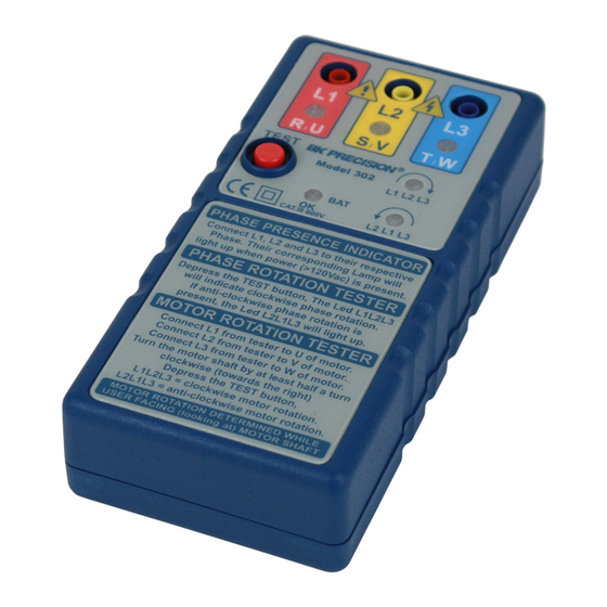
FRONT PANEL LAYOUT TEST L1 L2 L3 L2 L1 L3 CAT.III 600V PHASE PRESENCE INDICATOR Connect L1, L2 and L3 to their respective Phase. Their corresponding Lamp will light up when power (>120Vac) is present. PHASE ROTATION TESTER Depress the TEST button, The Led L1L2L3 will indicate clockwise phase rotation. -
Page 9: Principle Of How It Work
PRINCIPLE OF HOW IT WORK The tester has two separate circuits: The first circuit is the 3 Phase presence indicator, which is shown by the neon lamps and the second circuit is the three phase sequence indicator by LEDs. A low battery, with a Power On indicator circuitry is also present. 3 Phase Presence Indication circuit: This circuit uses neon lamps to indicate if a phase is present. -
Page 10: Preparation For Use
PREPARATION FOR USE Fuses: In doubt, check the fuses using a ohm meter. Please note that this instrument will not indicate anything, should the fuses be blown. Test Leads: Check the test leads for defects or cracks. Replace if cracked or damaged. -
Page 11: Specifications
SPECIFICATIONS ELECTRICAL Determination of the Phase Presence Nominal Voltage for Phase Presence Indication (the voltage required for the neon lamps L1, L2, L3 to lit up) ... From 100Vac to 600Vac. Frequency Range ........From 10Hz to 400Hz. Determination of the Phases Rotary Field Direction: Direction (the voltage required to have the direction LEDs L1-L2-L3 or L2-L1-L3 to indicates) ...... -
Page 12: Limited One-Year Warranty
LIMITED ONE-YEAR WARRANTY B&K Precision warrants to the original purchaser that its products and the component parts thereof, will be free from defects in workmanship and materials for a period of one year from date of purchase from an authorized B&K Precision distributor. -
Page 13: Service Information
SERVICE INFORMATION Warranty Service: Please return the product in the original packaging with proof of purchase to the address below. Clearly state in writing the performance problem and return any leads, probes, connectors and accessories that you are using with the device.
Need help?
Do you have a question about the 302 and is the answer not in the manual?
Questions and answers