
Subscribe to Our Youtube Channel
Related Manuals for GPI G20-012PO


Summary of Contents for GPI G20-012PO
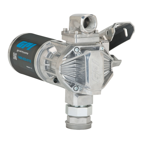
- Page 1 Product Owner’s Manual 20 GPM (76 L/min) 12V (dc) Fuel Transfer Pump Models G20-012PO, G20-012MD, G20-012AD (PATENT-PENDING) 3/2019 922138-01 Rev-...
- Page 2 Thank you for choosing a Great Plains Industries product, and congratulations on your purchase! Headquartered in the heartland of the U.S., GPI strives for integrity, innovation, continuous improvement, and dependability—values you will immediately recognize when using our products. The maintenance policies and procedures outlined in this manual emphasize our commitment to safety and our dedication to you as a customer.
-
Page 3: Before You Begin
Power Source Requirements Temp_Caution1.eps plug.eps • This manual covers 12V (dc) electric gear pump models G20-012PO, G20-012MD, and G20-012AD body_protection.eps • Do not attempt connection of any pump to a 24V (dc), 115V (ac) or oil.eps... -
Page 4: General Safety Instructions
GENERAL SAFETY INSTRUCTIONS IMPORTANT: It is your responsibility to: • Know and follow applicable national, state and local safety codes pertaining to installing and operating electrical equipment for use with flammable liquids. • Know and follow all safety precautions when handling petroleum fuels. •... -
Page 5: Specifications
SPECIFICATIONS G20-012PO G20-012MD G20-012AD Housing Aluminum Material Pump Rate 20 GPM (76 L/min) Duty Cycle Intermittent, 30 minute ON, 30 minute OFF Suction Lift Up to 9 ft. (2.7 m) Operating -20 °F to 125 °F (-29 °C to 52 °C) - Page 6 SPECIFICATIONS (CONTINUED) G20-012PO, G20-012MD, G20-012AD Dimensions A. Pump Assy Width 9.20 in. (23.36 cm) B. Pump Assy Height 9.24 in. (23.46 cm) C. Pump Assy Depth 11.62 in. (29.51 cm) Figure 1...
-
Page 7: Installation Instructions
INSTALLATION INSTRUCTIONS Coverplates protect the operator from moving parts. Never operate the pump without coverplates in place. Never apply electric power to the pump without coverplates in place. Always disconnect power before repairing or servicing. Mechanical Connections NOTE: All threaded fuel connections must be sealed with thread tape or a pipe thread sealing compound approved for use with petroleum fuels and tightened securely to prevent leakage. - Page 8 Using a 4mm Hex wrench, install nozzle cover using (1) M6-1.0 x 14mm BHCS in lower hole (see Figure 5). NOTE: For model G20-012PO only, DO NOT install nozzle cover until after power cord has been installed. See Install Power Cord (G20-012PO model) section.
- Page 9 INSTALLATION INSTRUCTIONS (CONTINUED) Outlet M6-1.0 x 20mm Adapter SHCS Nozzle Cover #222 O-ring M6-1.0 x 14mm BHCS Figure 5 Install Hose and Nozzle Wrap one end of the dispensing hose with three to four turns of thread tape and thread into outlet port. Tighten securely using an adjustable wrench.
- Page 10 Connection method to a battery will depend upon the application. If pump is to be installed in a CLASS I, DIVISION I location please contact GPI for the appropriate product. Install Power Cord (G20-012PO model) For installation in unclassified areas, the supplied power cord, fuse and strain relief grip may be used.
- Page 11 INSTALLATION INSTRUCTIONS (CONTINUED) Figure 6 Strain Relief M6 x 20mm SHCS Power Cord M6 x 14mm BHCS Green Ground Screw Black Wires Red Wires Figure 7 External Ground Screw Location Figure 7a Install Ground Wire A grounding connection is provided. It is identified as a green colored binding head screw in the electrical cavity (see Figure 7).
-
Page 12: Connect To A Power Source
INSTALLATION INSTRUCTIONS (CONTINUED) Connect to a Power Source NOTE: Please consult the Owner’s Manual for your vehicle before proceeding. IMPORTANT: The pump is designed for use with a 12 V (dc) power source. Do not attempt connection of any pump to a 24 V (dc), 115 V (ac) or 230 V (ac) power source. -
Page 13: Operation
OPERATION IMPORTANT: Always follow safety precautions when operating this equipment. Review the Safety Instructions. To prevent physical injury or property damage, observe precautions against fire or explosion when dispensing fuel. Do not operate the system in the presence of any source of ignition including running or hot engines, lighted tobacco products, gas or electric heaters, or any type of electronic device. -
Page 14: Motor Protector
OPERATION (CONTINUED) Motor Protector NOTE: This pump is equipped with a motor protective device that also serves as the ON/OFF switch. The motor protective device is not intended to provide branch protection. If motor is overloaded, the protective device trips and opens the circuit. This feature protects the motor from damage and must be reset manually. -
Page 15: Troubleshooting
TROUBLESHOOTING Symptom Possible Cause(s) Corrective Action Motor does not run 1. Fuse blown 1. Inspect fuse in fuse holder on power cord. If blown, replace 2. Switch defective 2. Remove switch coverplate and inspect switch. Replace, if necessary 3. Switch or electrical 3. - Page 16 TROUBLESHOOTING (CONTINUED) Symptom Possible Cause(s) Corrective Action Low flow rate 1. Strainer partially clogged 1. Remove the strainer coverplate. Remove and clean the strainer. Install again 2. Poor connections 2. Make sure electrical connections are secure. or low voltage Also check battery voltage 3.
- Page 17 TROUBLESHOOTING (CONTINUED) Symptom Possible Cause(s) Corrective Action Switch fails to operate 1. Switch or electrical 1. Inspect for blown fuse, connections faulty defective wiring or switch, motor or improper electrical connections. Refer to Switch Replacement instructions in the Repair Section 2.
-
Page 18: Maintenance
MAINTENANCE NOTE: This pump is designed for minimum maintenance. The motor bearings are self-lubricating. Inspect the pump and components regularly for fuel leaks and make sure the hose and power cord are in good condition. Keep the pump exterior clean to help identify leaks. IMPORTANT: Do not use this pump for water, chemicals or herbicides. - Page 19 REPAIR IMPORTANT: Carefully inspect all parts for wear or damage. Replace components, as necessary. The Illustrated Parts List gives information on replacement parts and kits. Review the Safety Instructions before proceeding. Observe precautions against electrical shock when servicing the pump. Always disconnect power before repairing or servicing.
- Page 20 REPAIR (CONTINUED) Replace Gears Turn the pump OFF and disconnect from power. Using 5mm hex wrench, remove the gear coverplate and O-ring (see Figure 12). Remove the gears. Inspect gears for wear and damage. Replace, as necessary. Wipe the gear cavity with a clean cloth. Replace the gears.
- Page 21 REPAIR (CONTINUED) Clean and Replace Bypass Poppet Turn the pump OFF and disconnect from power. Using a 5mm Hex wrench, remove the coverplate from the pump. With a 10mm Hex wrench remove the pipe plug from the coverplate, and remove the bypass poppet spring, O-ring, bypass poppet and orifice seal (see Figure 13).
- Page 22 REPAIR (CONTINUED) Replace Motor Shaft Seal Turn the pump OFF and disconnect from power. Using a 5mm Hex wrench, remove the (4) M6 x 80mm SHCS on gear coverplate and (1) M6 x 35mm SHCS located on back of pump housing.
-
Page 23: Replace Power Switch
REPAIR (CONTINUED) Replace Power Switch Turn the pump OFF and disconnect from power. Using a 4mm Hex wrench remove the M6 BHCS and nozzle cover. Remove the (4) M6 SHCS and electrical coverplate from the motor housing. Remove the (1) #10 truss head screw and switch bracket with switch assembly (see Figure 15). -
Page 24: Parts And Service
PARTS & SERVICE For warranty consideration, parts, or other service information, please contact your local distributor. If you need further assistance, contact the GPI Customer Service Department in Wichita, Kansas, during normal business hours. - Page 25 IMPORTANT: Please contact GPI before returning any parts. It may be possible to diagnose the trouble and identify needed parts in a telephone call. GPI can also inform you of any special requirements you will need to follow for shipping fuel dispensing equipment.
- Page 26 NOTES...
- Page 27 NOTES...
- Page 28 B. the product has been subjected to neglect, misuse, abuse or damage or has been installed or operated other than in accordance with the manufacturer’s operating instructions. To make a claim against this warranty, contact the GPI Customer Service Department at 316-686-7361 or 800-835-0113. Or by mail at: Great Plains Industries, Inc.
Need help?
Do you have a question about the G20-012PO and is the answer not in the manual?
Questions and answers