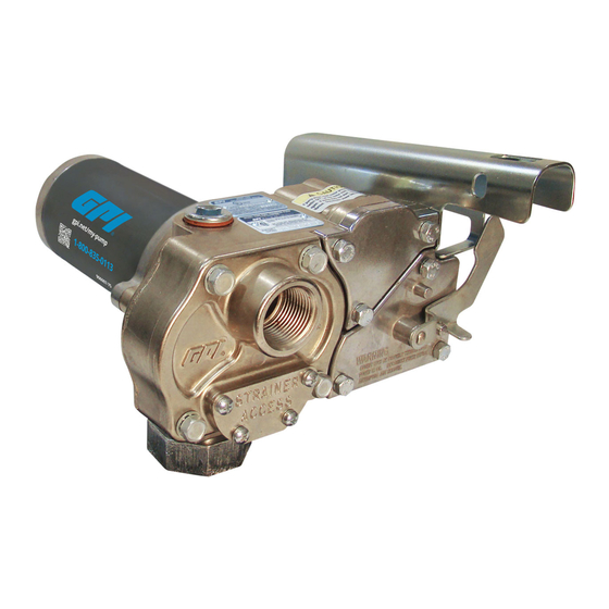
GPI M-150S Product Owners Manual
15-18 gpm (57-68 l/min) 12v & 24v (dc) fuel transfer pump
Hide thumbs
Also See for M-150S:
- Product owners manual (17 pages) ,
- Troubleshooting manual (46 pages) ,
- Product owners manual (29 pages)

Related Manuals for GPI M-150S


Summary of Contents for GPI M-150S
- Page 1 Product Owner’s Manual 15-18 GPM (57-68 L/min) 12V & 24V (dc) Fuel Transfer Pump Models: M-150S, M-180S, M-240S SAVE THESE INSTRUCTIONS 922123-01 Rev B 12/2020 per ECN 5821...
- Page 2 Thank you for choosing a Great Plains Industries product, and congratulations on your purchase! Headquartered in the heartland of the U.S., GPI strives for integrity, innovation, continuous improvement, and dependability—values you will immediately recognize when using our products. The maintenance policies and procedures outlined in this manual emphasize our commitment to safety and our dedication to you as a customer.
- Page 3 NOTES...
-
Page 4: Before You Begin
(2) Ring Terminals (Item F) and (1) Wire Connector (Item G) hand_protection.eps Resp_protection2.eps • (1) 12 foot (3.6 m) Dispensing Hose (Item H) (M-150S-AU & -MU, M-180S- measure.eps Electrical_Caution.eps AU & -ML, and M-240S-MU) or (1) 10 foot (3.0 m) Dispensing Hose... - Page 5 UNPACKING (CONTINUED) (P) Lockable Contents (Continued): Nozzle Holder (N) Manual Shut-off Nozzle (M) Automatic Shut-off Nozzle (A) Spin Collar (Q) Standard Nozzle Holder (H or J) Dispensing Hose (B) Direct Mount (F) Ring Terminals (G) Wire Connector (K) Reducer (D) Tank Adapter (E) Fuse (C) Fiber Gasket...
- Page 6 INTERNATIONAL ISO SAFETY SYMBOLS This symbol indicates a general warning to the user. See additional specific warnings. This symbol indicates electrical shock hazard. Follow proper installation and maintenance instructions in this manual. This symbol indicates hot surface. Take care to avoid coming into contact with hot surface.
-
Page 7: General Safety Instructions
GENERAL SAFETY INSTRUCTIONS IMPORTANT: It is your responsibility to: • Know and follow applicable national, state and local safety codes pertaining to installing and operating electrical equipment for use with flammable liquids. • Know and follow all safety precautions when handling petroleum fuels. •... -
Page 8: Specifications
SPECIFICATIONS M-150S-AU M180S-ML M-150S-EM M240S-MU M-150S-MU M180S-AU Lightweight, corrosion-resistant, cast aluminum body Housing Material Up to 15 GPM Up to 18 GPM Up to 15 GPM Pump Rate (57 LPM) (68 LPM) (57 LPM) Duty Cycle 30 minute ON, 30 minute OFF Manual Nozzle: Up to 5.5 ft. - Page 9 SPECIFICATIONS (CONTINUED) M-150S-AU & -MU & -PO M-150S-EM & -E-PO M-180S and M-240S Dimensions Inches (cm) A. Pump Ass’y Width 9.19 (23.34) 9.13 (23.20) B. Pump Ass’y Height 5.42 (13.77) 4.95 (12.57) C. Pump Ass’y Height 7.00 (17.78) 6.74 (17.12) w/Nozzle Holder D.
-
Page 10: Installation Instructions
Install Tank Adapter and Suction Pipe (for all models except M-150S-EM & M-150S-E-PO) Wrap the 2" threaded end of the tank adapter with three or four turns of thread tape (see Figure 3). Using a pipe wrench, tighten the adapter snugly into the fuel tank. - Page 11 INSTALLATION INSTRUCTIONS (CONTINUED) Install Suction Pipe (for model M-150S-EM & M-150S-E-PO) Wrap the threaded mount of the fuel pump with three or four turns of thread tape. NOTE: For Aluminum Tank Installation - To prevent thread galling of aluminum fittings, always prepare the threads for assembly using an anti-seize compound such as Loctite®...
- Page 12 INSTALLATION INSTRUCTIONS (CONTINUED) Install Pump on Tank (model M-150S-EM & M-150S-E-PO) Clean the tank interior of all dirt and foreign material. Carefully lift pump / suction pipe assembly and insert suction pipe into the tank opening. Position the pump mount and tighten securely, making sure the threads are not cross-threaded;...
-
Page 13: Connect To A Power Source
NOTE: Please consult the Owner’s Manual for your vehicle before proceeding. IMPORTANT: The pump is designed for use with a 12 Volt (M-150S and M-180S) or 24-Volt (M-240S) DC power source. Do not attempt installation on a 115 or 230 Volt AC system. -
Page 14: Operation
IMPORTANT: After running the pump for a maximum of 30 minutes, allow it to cool for 30 minutes. Motor Protector NOTE: The M-150S and M-180S pumps have a motor protector that provides added protection against motor damage. It must be reset manually. -
Page 15: Troubleshooting Guide
Replace, if necessary 3. Switch or electrical 3. Inspect for damaged motor connections are faulty protector, defective wiring or (models M-150S switch, or improper electrical and M-180S) connections. Replace as needed and reinstall 4. Circuit breaker tripped 4. - Page 16 TROUBLESHOOTING GUIDE (CONTINUED) Symptom Possible Cause(s) Corrective Action Motor runs but does 7. System air leak 7. Tighten all pump fittings and pump (continued) connections. Inspect suction pipe for leaks or damage 8. System air lock 8. Occurs if external filter, meters or an off-the-shelf automatic nozzle is used.
- Page 17 3. Turn off switch. Allow motor activated to cool, then turn on switch 4. Switch or electrical 4. Inspect for damaged motor connections faulty protector, blown fuse, (models M-150S and defective wiring or switch, M-180S) or improper electrical connections. Replace as needed and re-install 14-EN...
- Page 18 TROUBLESHOOTING GUIDE (CONTINUED) Symptom Possible Cause(s) Corrective Action Rapid overheating of motor 1. Duty cycle too long 1. Pump operation should not exceed the standard duty cycle of 30 minutes ON, and 30 minutes OFF. Allow the pump to cool for 30 minutes 2.
-
Page 19: Maintenance
MAINTENANCE NOTE: This pump is designed for minimum maintenance. The motor bearings are sealed and require no lubrication. Inspect the pump and components regularly for fuel leaks and make sure the hose and power cord are in good condition. Keep the pump exterior clean to help identify leaks. - Page 20 REPAIR IMPORTANT: Carefully inspect all parts for wear or damage. Replace components, as necessary. The Illustrated Parts List gives information on replacement parts and kits. Review the Safety Instructions before proceeding. Observe precautions against electrical shock when servicing the pump. Always disconnect power before repairing or servicing.
- Page 21 REPAIR (CONTINUED) Clean Bypass Poppet Turn the pump OFF and disconnect from power. Using a 1/2” drive socket wrench, remove the pipe plug from the top outlet port (see Figure 16). Remove the gear coverplate and O-ring from the pump housing. Pull the drive key and two gears from the pump (see Figure 17).
- Page 22 REPAIR (CONTINUED) Replace Bypass Poppet O-ring To remove or replace the bypass poppet: As with cleaning, push down on the poppet until the O-ring is exposed. Remove the O-ring with a small screwdriver or similar tool. Take care not to damage the poppet or O-ring (see Figure 19). From inside the housing, push the poppet and spring upward and pull through the top outlet port (see Figure 20).
-
Page 23: Replace Motor
REPAIR (CONTINUED) Replace Motor Shaft Seal Turn the pump OFF and disconnect from power. Remove the gear coverplate, gears and drive key as described in Gear Replacement instructions. Remove the (3) 1/4-20 x 3/4 inch SEMS screws and motor from the pump housing (see Figure 22). -
Page 24: Replace Power Switch
REPAIR (CONTINUED) Replace Power Switch Turn the pump OFF and disconnect from power. Remove the switch coverplate from the pump housing (see Figure 24). Remove the torx head screw, then remove the switch assembly (see Figure 25). Unscrew both blade terminals and remove red pump wires from the back of the switch (see Figure 26). - Page 25 NOTES 22-EN...
- Page 26 REPAIR PARTS ILLUSTRATION FOR M-150S-AU, M150S-MU, M180S-ML, M180S-AU, and M-240S-MU Motor Length Measurement REPAIR PARTS LIST FOR FOR M-150S-AU, M-150S-MU, M-180S AND M-240S Ref. Description Part Number: Qty. Gear Kit - Includes 2 Gears & Drive Key 110906-1 Wet Seal Kit...
- Page 27 REPAIR PARTS ILLUSTRATION FOR M-150S-EM REPAIR PARTS LIST FOR M-150S-EM Ref. Description Part Number: Qty. Gear Kit - Includes 2 Gears & Drive Key 110906-1 Wet Seal Kit 110907-1 Gear Coverplate O-ring ▲ Strainer Coverplate O-ring ▲ Bypass Poppet O-ring ▲ Motor Shaft Seal ▲ Switch Assembly 110277-05...
- Page 28 B. the product has been subjected to neglect, misuse, abuse or damage or has been installed or operated other than in accordance with the manufacturer’s operating instructions. To make a claim against this warranty, contact the GPI Customer Service Department at 316-686-7361 or 800-835-0113. Or by mail at: Great Plains Industries, Inc.
Need help?
Do you have a question about the M-150S and is the answer not in the manual?
Questions and answers
wiring diagram of 150s pump