Advertisement
Advertisement

Related Manuals for Potensic U47


Summary of Contents for Potensic U47
- Page 1 Operation Guide...
-
Page 2: Table Of Contents
Catalog Instruction for Drone and Controller Installing & Removing Spare Parts Pre-Flight Checklist Pre-Flight Operation Instructions Functions Using App Precaution about taking photos Spare Parts Troubleshooting... -
Page 3: Instruction For Drone And Controller
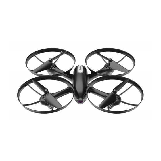
Instruction For Drone And Controller Drone Front Left Protection Right Protection Ring Ring Propeller A Propeller B Drone Cover Left Housing Right Power Switch Propeller B Propeller A Rear Camera Front LED Front LED (Green) (Green) Drone Bottom Housing Rear LED Rear LED (Red) (Red) - Page 4 Exploded View...
- Page 5 Name Name Propeller plug Receiving plate holder A Propeller Camera plate Rotary gear Battery adapter plate Drone bottom Housing Right rear light board (red light/white plug) Landing gear lampshade Copper cup Shock proof tape Motor frame Lens press B Main shaft steel pipe lens organic plate Steel pipe fixer Power button...
- Page 6 Trimmer Mode Button High/Medium/Low Speed (Press Down) Mode (Press Down) Controller Button Functions Left Stick: Move the Stick to forward / backward / left / right to fly the drone up / down / turn left / turn right. Right Stick: Move the Stick to forward / backward / left / right to fly the drone forward / backward / left / right.
- Page 7 Phone Installation Instruction 1. Take out the phone holder and insert into the controller(Picture 3). 2. Unfold the phone holder ( Picture 4/5), put the phone into the holder, then release the clamp, and the phone will be fixed on the holder( Picture 6). 3.
- Page 8 Propeller installation diagram When installing, put the propeller hole aims to the drone shaft hole, and then press down until bottom, tighten it with screw, and then put on propeller cover( Pic 8); when disassembling, loose the screw and then pull out the propeller. Notice: When installing, please make sure correct propeller in its right place, otherwise the drone can not work well.
- Page 9 Diagram of loading and unloading of protective frame When loading, aim the buckle 1 of the protection ring at the position 1 on the bracket and push it to the bottom (Picture 11),then aim the protective ring clasp 2 at the position 2 on the bracket and press down to the right position(Picture 12). When unloading, first pull up position 2, then pull out position 1 outwards(Picture) Button Placement 2 Buckle 1...
-
Page 10: Pre-Flight Checklist
Receiver board wire diagram Front Positive / Negative wire pad Camera board socket Rear Pre-Flight Checklist 1. Ensure that the drone battery and controller batteries are fully charged. 2. Ensure that the left stick of the controller is in the middle position. 3. - Page 11 Flight Instruction Frequency Pairing Turn on the transmitter switch and the power indicator light flashes rapidly. Power switch (Press down) Pull the Left Stick all the way down to the lowest position and then release. The Left Stick will back to the middle position automatically.
- Page 12 Emergency Stop When the drone is in emergency situation and going to hit the walking people or obstacle etc., press the Take Off / Landing / Emergency Stop Button immediately and hold it for more than 1s,the propellers will stop immediately. Tip: Do not use the emergency stop function unless in emergency situation.
- Page 13 Flying Control Trimmer mode Forward and backward trimmer Left and right side flying trimmer When taking off, if the drone tilts forward, press When take off, if the drone tilts to left, then press down the trimmer button, and push the right down the trimmer button and push the right stick stick backwards.
-
Page 14: Functions
Functions Introduction Altitude Hold Mode Intelligent flight control system is able to calculate the hovering position, more stable control feature, and makes it easier for beginners to control. Release the stick, the drone will keep hovering automatically to enable single hand operation and more clearly aerial photography. - Page 15 Heading Hold Mode Drones generally have a front and rear indicated by LED lights or colored propellers. By default, the users are required to tell the front and the rear of the drone when flying. Under heading hold mode, the users can operate the drone without worrying about the orientation (left is left and right is right all the time, regardless of where your drone is pointing at).Heading Hold Mode is designed for beginners and the users who fly the drone in daylight or at a far distance or...
- Page 16 Know your APP Download and install APP: Potensic This software is suitable for mobile phones in the IOS and Android system, please surf the mobile phone application store website to download and install it.
-
Page 17: Spare Parts
Spare Parts (Sold separately) These are the components for choice below. For your convenient purchase, now we list each part for you, you can purchase ones you want from local distributor. Drone Cover Drone Bottom A Propeller B Propeller Housing Housing Left protection ring Right protection ring Landing gear... - Page 18 B propeller motor Left Front Lamp Right Front Lamp Right Rear Lamp ( Red blue wire/ Board (Green LED / Board (Green LED / Board (Red LED / red connector) White Connector) Red Connector) White connector) Left Rear Lamp Receiver Board Camera Board Drone Battery Board (Red LED /...
-
Page 19: Troubleshooting
Troubleshooting Problem Problem Cause Solution 1. Low battery. 1. Replace the controller battery. 2. Install the batteries following the 2. The batteries are incorrectly controller polarity indicators. positioned. indicator 3. Clean between the battery and the light is off. 3. Poor Contact. battery contacts. - Page 20 FCC Note This equipment has been tested to comply with the limits for a Class B digital device, pursuant to Part 15 of the FCC Rules. These limits are designed to provide reasonable protection against harmful interference in a residential installation.
Need help?
Do you have a question about the U47 and is the answer not in the manual?
Questions and answers