Table of Contents
Advertisement
Via Acquanera, 29
22100 Como
tel. 031.526.566 (r.a.) fax 031.507.984
info@calpower.it
www.calpower.it
USER'S MANUAL
Programmable HV Power Supply
Model IT6700 Series
IT6723/IT6724/IT6723C
/IT6724C/IT6723B/IT6724B/IT6726B
/IT6723H/IT6724H/IT6726H
/IT6723G/IT6724G/IT6726G/IT6726V
©Copyright All Rights Reserved
Ver1.1/OCT, 2012/ IT6700
1
IT6700 User manual
User Manual
Advertisement
Table of Contents

Related Manuals for ITech IT6724


Summary of Contents for ITech IT6724
- Page 1 IT6700 User manual Via Acquanera, 29 22100 Como tel. 031.526.566 (r.a.) fax 031.507.984 info@calpower.it www.calpower.it USER’S MANUAL Programmable HV Power Supply Model IT6700 Series IT6723/IT6724/IT6723C /IT6724C/IT6723B/IT6724B/IT6726B /IT6723H/IT6724H/IT6726H /IT6723G/IT6724G/IT6726G/IT6726V ©Copyright All Rights Reserved Ver1.1/OCT, 2012/ IT6700 User Manual...
-
Page 2: Table Of Contents
IT6700 User manual IT6700 Series Programmable HV Power Supplies ............... 3 Security ..........................3 Security regulation ........................ 3 Safety symbols ........................3 Certification and Quality Assurance ..................3 Introduction ........................... 5 Chapter1 Inspection and Installation ....................6 ... -
Page 3: It6700 Series Programmable Hv Power Supplies
IT6700 User manual IT6700 Series Programmable HV Power Supplies Security Please do not install replacement parts in the instrument, or perform any unauthorized modification. Please send the instrument to our company's maintenance department for maintenance, to ensure its security features. Please refer to the manual for specific information warning or precautions to avoid personal injury or equipment damage. - Page 4 IT6700 User manual Warranty Service For the warranty service or repair the product, the product must be returned to the designated maintenance units. Return the product to us for warranty service, the customer should pre-pay the one-way Freight to the maintenance department. and our company is responsible for the return shipping cost.
-
Page 5: Introduction
Output voltage and current values accordance with procedure • • Can use the knob to adjust the voltage and current • Can adjust the knob stepping using the cursor Model Voltage Current Power IT6723 850W IT6724 1500W IT6723B 150V 850W IT6724B 150V 1500W IT6723H 300V... -
Page 6: Chapter1 Inspection And Installation
IT6700 User manual Chapter1 Inspection and Installation Power supply is a high level safety equipment, there is a protected ground terminal. Before Installation or operation, please read the safety signs and instructions in this manual 1.1 Inspection After received the power supply, follow these steps to check it: 1. -
Page 7: The Size Of The Power Supply
Drawing1.1 To rack mount a single instrument, order rack mount kit IT-E151 Drawing1.2 To rack mount two instruments side-by-side, order rack mount kit IT-E151, you needn’t to use the front cover panel. 1.3 The size of the power supply 1.SizeofIT6723/IT6724/IT6723B/IT6724B/IT6723C/IT6724C/IT6723H/IT6724 H/IT6723G/IT6724G: 214.5mmW×88.2mmH×445mmD *refer to the... - Page 8 IT6700 User manual Unit:mm Size of IT6726H/IT6726G/IT6726V/IT6726B: 439mmW×88.2mmH×462mmD User Manual...
- Page 9 IT6700 User manual User Manual...
-
Page 10: Chapter 2 Quick Start
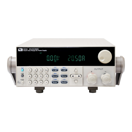
Help you make better use of this series of power supply. 2.1 The front and rear panel description FrontpanelofIT6723/IT6724/IT6723B/IT6724B/IT6723C/IT6724C/IT6723H/IT6724H/IT672 3G/IT6724G: VFD display Rotary knob... - Page 11 Compound key, the local switch key and power switch Number keys and ESC Function keys UP、DOWN, LEFT and RIGHT key, to move cursor Rotary knob Rear panel of IT6723/IT6724/IT6723B/IT6724B/IT6723C/IT6724C/IT6723H/IT6724H/IT67 23G/IT6724G: Cooling fans RS232 Communication interface USB Communication interface GPIB Communication interface...
-
Page 12: Key Introduction
IT6700 User manual Rear panel of IT6726H/IT6726G/IT6726V/IT6726B: Cooling fans RS232 Communication interface USB Communication interface GPIB Communication interface AC power socket Fuse Output terminal 2.2 Key introduction Key description, see the table below: Name and the function Keys Compound key,co-work with OVP、Menu、Save、Trigger、Lock Shift Local switch key, switch from remote mode to local operation mode Local... -
Page 13: Vfd Indicator Description
IT6700 User manual relevant Parameters for the power supply Callback key to call up a set value of system parameters already Recall Save stored / storage key, to save system parameter settings Meter key, to switch from value set panel and the actual output value Meter Meter Enter key, to confirm the number entered and operation / trigger... -
Page 14: Chapter 3 Power On Check
IT6700 User manual Chapter 3 power on check This chapter will introduce the procedure of power on check, including pre-check and output check, to make sure the IT6700 series power supply can power on and work normally on the original state. 3.1 power on Pre-check Before operate the power supply, please read the following safty guide: Warning:The power supply is shipped from the factory with a power-line cord... -
Page 15: System Self-Check
Model Fuse Specifications(220VAC) Fuse Specifications(220VAC) T15AT 250V T15AT 250V IT6723/IT6723B/IT6723C/I T6723H/IT6723G T15AT 250V Not available IT6724/IT6724B/IT6724C/I T6724H/IT6724G T20AT 250V Not available IT6726H/IT6726G/IT6726V /IT6726B 4) How to exchange the fuse Open the fuse box: Use a screwdriver to push and turn the fuse box on the rear panel of the power supply, refer to the below picture. -
Page 16: Output Checkout
IT6700 User manual If the calibration data in EEPROM is lost, then VFD will display (about 1S) as below: CAL LOST If the factory calibration data in EEPROM is lost, and then the VFD will display(about 1 S) as below: FACT LOST 3.2 Output Checkout The following procedures check to ensure that the power supply develops its rated... -
Page 17: Chapter4 Technical Specification
IT6700 User manual 8) Make sure that the current can be adjusted from 0 to full rated value. 9) Turn off the output of the power supply, and remove the short wire. Chapter4 technical specification This chapter will introduce the main technical parameters of IT6700H/IT6700G,such as rated voltage/current/power and so on. - Page 18 IT6700 User manual Parameters IT6723 IT6724 0~80V voltage Rated values 0~40A current ( 0 °C~40 °C) 850W 850W power ≤0.01%+10mV Load regulation voltage (%of output+offset) ≤0.1%+20mA current ≤0.01%+10mV Line regulation voltage (%of output+offset) ≤0.1%+20mA current 10mV voltage Setup resolution 10mA...
- Page 19 IT6700 User manual Parameters IT6723B IT6724B IT6726B 0~80V 160V voltage Rated values 0~40A current ( 0 °C~40 °C) 3000W 850W 3000W power ≤0.01%+60mV ≤0.01%+10mV Load regulation voltage (%of output+offset) ≤0.1%+20mA ≤0.1%+20mA current ≤0.01%+10mV ≤0.01%+60mV Line regulation voltage (%of output+offset) ≤0.1%+20mA ≤0.1%+20mA current 10mV...
- Page 20 IT6700 User manual Parameters IT6723H IT6724H 0 ~300V voltage Rated values 0~10A current ( 0 °C~40 °C) 850W 1500W power ≤0.01%+60mV Load regulation voltage (%of output+offset) ≤0.1%+20mA current ≤0.01%+60mV Line regulation voltage (%of output+offset) ≤0.1%+20mA current 100mV voltage Setup resolution 10mA current 100mV...
- Page 21 IT6700 User manual IT6724G Parameters IT6723G 0~600V voltage Rated values 0~5A current ( 0 °C~40 °C) 850W 1500W power ≤0.01%+100mV Load regulation voltage (%of output+offset) ≤0.1%+10mA current ≤0.01%+100mV Line regulation voltage (%of output+offset) ≤0.1%+10mA current 100mV voltage Setup resolution 10mA current 100mV voltage...
-
Page 22: Supplementary Characteristic
0-40℃ ≤0.1%+30mA ≤0.1%+20mA ≤0.1%+20mA current 0-40℃ 0-40℃ 0-40℃ Working temperature 439mmW×88.20mmH×462mmD 439mmW×88.20mmH×462mmD Dimension(mm) 13Kg 13Kg Weight(net) 4.2 Supplementary parameters Memory :9×8 groups suggested calibrationfrequency:1time/year Max input AC power IT6723/IT6723B/IT6723H/T6723G 1100VA IT6723C 1150VA IT6724/IT6724B/IT6724H/IT6724G 1850VA IT6724C 1900VA IT6726H/IT6726G/IT6726V/IT6726B 3700VA User Manual... -
Page 23: Chapter5 Basic Operation
IT6700 User manual Radiating mode :Fans Operation temperature:0 to 40 °C Storage temperature:-20 to 70 °C. Humidity :Max humidity: 80% Chapter5 Basic operation This chapter will introduce the basic operation of IT6700 series power supply,including the following subdivisions: Local/remote mode ... -
Page 24: Current Setup
IT6700 User manual 5.3 Current Setup I-set I-set You can set current within the range of rated current value. When you press button, the button will be lit. This indicates that you can set current. There are three ways to set output current through front panel. -
Page 25: Save/Recall Operation
IT6700 User manual 5.7 Save/recall Operation Customer can save some often-used parameters in nonvolatile memory. You can use Recall the button (Shift)、 (Save) button or SCPI order *SAV、*RCL to achieve this function. Saving parameters include: 1. setting voltage 2. setting current 3. OVP value 4. OCP value Saving operation: Recall Recall... - Page 26 IT6700 User manual Address can be set within 0-30 GPIB ADDR 4800 9600 19200 BAUD 38400 57600 115.2K RS232 COMM (GPIB) NONE 8BIT EVEN 8BIT NONE 8BIT ODD 8BIT SIGNAL Address can be set within MODE 0-30 Select USBcommunication interface Disable the key sound BEEP (ON) Enable the key sound...
-
Page 27: Menu Functions
IT6700 User manual the first six number of SN SN-1 XXXXXX the middle six number of SN SN-2 XXXXXX the last six number of SN SN-3 XXXXXX Exit the information menu EXIT Exit the main menu EXIT MENU Note: Pressing button can enable you to quit any function setting. - Page 28 IT6700 User manual Communication (COMM ) Our unit has provided three standard communication interfaces: RS232/USB/GPIB.In this option, you can select the communication interface according to your demands. The range of GPIB address is 0-30. Besides, we have multi-baudrate to be chosen in RS232 mode---4800,9600,19200,38400,57600,115.2K.Data bit is 8,Check digit have three choices: NONE,ODD,EVEN.Before you begin to carry out communication,please make sure the configure in our unit agrees with PC configure.
- Page 29 IT6700 User manual GRP3-GRP8 by parity of reasoning. Detailed Save and Recall operation refer to chapter 5.7. Timer Set(TIMER SET) This item is used to set the “time on- load” function, time range 0.1-99999S .In ON mode,the indicator light “Timer” will be lit on the VFD screen.When output of power supply is opened,timer will begin to work,after reaching the definite time,output will be off automatically.If in OFF mode,the timer function will not be enabled.The default set is OFF Reset(RESET)...
- Page 30 IT6700 User manual Enter (8) VFD display NEXT >YES,press to confirm. (9) Repeat the steps from 5) to 8) and set the four steps’ voltage/current and delay time separately. When screen display NEXT>YES in the fourth step edit process,please press Enter to select NEXT >NO,press to confirm.
-
Page 31: Ovp Function
IT6700 User manual Trigger Trigger 5.10 OVP function V-set V-set IT6700 series power supply provide OVP function,press button can (Shift)+ enable you to set the over voltage protection level.Over voltage may caused by internal defect or customer’s incorrect operation(such as output voltage rising),or a too high external voltage.Once OVP function is triggered,the output will be off immediately and “OVP”... - Page 32 IT6700 User manual Remote sense function Remote sense can adjusted at the output voltage of the device under test, this feature allows to compensate the voltage drop on the wire between the front panel terminals of the power supply and the device under test. Use local sense :...
-
Page 33: Chapter6 Remote Operation Mode
IT6700 User manual Chapter6 Remote Operation Mode IT6700 series power supply three standard communication interface: RS232, USB, GPIB, the user can choose any one of them to implement a communication with the computer. 6.1 RS232 interface There is a DB9 connector at the rear of the power supply, when connect to computer, you need to select a cable with COM port on both side;... -
Page 34: Usb Interface
IT6700 User manual RS-232 plug pins Pin number Description No connection TXD, transfer date RXD, receive data No connection GND, ground No connection CTS, clear transfer RTS, ready to transfer No connection RS-232 Troubleshooting: If there is RS-232 connection problem, check the following: Computer and power supply must configure the same baud rate, parity, data bits and flow control options. -
Page 35: Gpib Interface
IT6700 User manual Interface Receiver REN_CONTROL, GO_TO_LOCAL, and LOCAL_LOCKOUT request. Interface receive MsgID = TRIGGER USBTMC order information, and will pass TRIGGER order to the functional layer. Power USB488 device functions described as follows: devices can read all of the mandatory SCPI orders. device is SR1 enabled. - Page 36 If you have a problem , follow these steps: 1 Check the documentation that come with the product 2 Visit the ITECH online service Web site is www.itechate.com ,ITECH is avaliable to all ITECH customers. It is the fastest source for up-to-date product information and expert...
Need help?
Do you have a question about the IT6724 and is the answer not in the manual?
Questions and answers