Table of Contents
Advertisement
Electronic copies of the most current TSM issue can be found on the Viking Pump website at www.vikingpump.com
CONTENTS
Special Information . . . . . . . . . . . . . . . . . . . 1
Maintenance . . . . . . . . . . . . . . . . . . . . . . 3
Disassembly . . . . . . . . . . . . . . . . . . . . . . 5
Assembly . . . . . . . . . . . . . . . . . . . . . . . . 6
Mechanical Seal Replacement . . . . . . . . . . . . . 7
Seal Removal. . . . . . . . . . . . . . . . . . . . . 7
Seal Installation. . . . . . . . . . . . . . . . . . . . 8
Thrust Bearing Adjustment . . . . . . . . . . . . . . . 9
Installation of Carbon Graphite Bushings . . . . . . . .10
Pressure Relief Valve Instructions . . . . . . . . . . .10
Disassembly . . . . . . . . . . . . . . . . . . . . .10
Assembly . . . . . . . . . . . . . . . . . . . . . . .10
Pressure Adjustment . . . . . . . . . . . . . . . . .10
Heat Cartridges . . . . . . . . . . . . . . . . . . . . .11
INTRODUCTION
The illustrations used in this manual are for identification
purposes only and cannot be used for ordering parts. Obtain
a parts list from the factory or a Viking representative. Always
give a complete name of part, part number and material with
the model number and serial number of pump when ordering
repair parts. The unmounted pump or pump unit model
number and serial number are on the nameplate.
Model Chart Number
UNMOUNTED PUMP
Packed
Mech. Seal
N323A
N4323A
N323E
R4323A
R323A
RS4323A
RS323A
N4324A
N324A
N4324AH
N324AH
N324E
N324EH
R324A
R4324A
N327A
N4327A
R327A
R4327A
RS327A
RS4327A
This manual deals only with Series 324A, 324AH, 4324A,
4324AH, 324E, 324EH, 323A, 323E, 4323A, 327A, 4327A
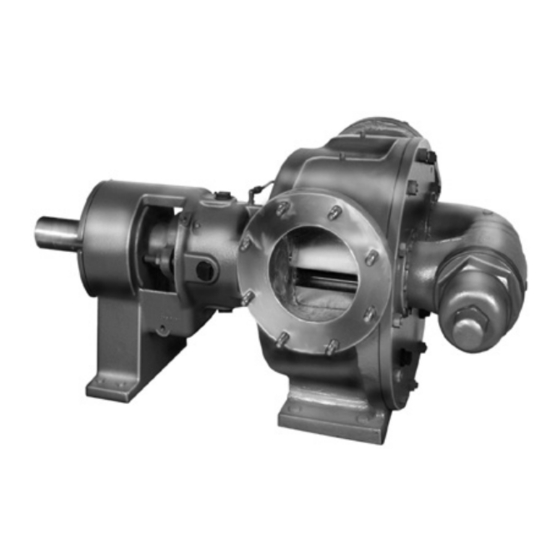
Heavy Duty Bracket Mounted Pumps. Refer to Figures 1
through 12 for general configuration and nomenclature used
in this manual. Pump specifications and recommendations are
listed in Catalog Section 630, Viking Universal Seal Pumps.
VIKING PUMP, INC.
TECHNICAL SERVICE MANUAL
UNIVERSAL SEAL HEAVY DUTY PUMPS
SERIES 324A/AH/E/EH & 4324A/AH CAST IRON
SERIES 327A & 4327A STAINLESS STEEL
UNITS
Units are designated by the
unmounted pump model
numbers followed by a
letter indicating drive style.
P = Commercial Speed
Reducer
•
A Unit of IDEX Corporation
SERIES 323A/E & 4323A STEEL
SIZES N, R AND RS
N AND R SIZES
(R SIZE SHOWN)
SPECIAL INFORMATION
DANGER !
Before opening any Viking pump liquid
chamber (pumping chamber, reservoir,
relief valve adjusting cap fitting, etc.)
Be sure:
1. That any pressure in the chamber has
been completely vented through the
suction or discharge lines or other
appropriate openings or connections.
2. That the driving means (motor,
turbine, engine, etc.) has been "locked
out" or made non-operational so that
it cannot be started while work is
being done on pump.
3. That you know what liquid the
pump has been handling and the
precautions necessary to safely
handle the liquid. Obtain a material
safety data sheet (MSDS) for the
liquid to be sure these precautions
are understood.
Failure
to
precautionary measures may result in
serious injury or death.
•
Cedar Falls, IA 50613 USA
SECTION
TSM 630.3
PAGE
1 OF 12
ISSUE
L
FIGURE 1
follow
above
listed
Advertisement
Table of Contents

Subscribe to Our Youtube Channel
Related Manuals for Viking pump 323A Series


Summary of Contents for Viking pump 323A Series
-
Page 1: Table Of Contents
Electronic copies of the most current TSM issue can be found on the Viking Pump website at www.vikingpump.com TECHNICAL SERVICE MANUAL UNIVERSAL SEAL HEAVY DUTY PUMPS SECTION TSM 630.3 SERIES 323A/E & 4323A STEEL PAGE 1 OF 12 SERIES 324A/AH/E/EH & 4324A/AH CAST IRON ISSUE SERIES 327A &... - Page 2 ● You know what material the pump has been For weight of the pump alone (which does not include handling, have obtained a material safety data the drive and/or base plate) refer to the Viking Pump sheet (MSDS) for the material, and understand product catalog.
-
Page 3: Maintenance
ROTATION: Viking pumps operate equally well in a Relief valve adjusting screw cap must always point clockwise or counterclockwise rotation. Shaft rotation towards suction side of pump. If pump rotation is determines which port is suction and which is discharge. reversed, remove pressure relief valve and turn end for end. - Page 4 SUGGESTED REPAIR TOOLS: The following tools must be 4. Mechanical seal installation sleeve available to properly repair Universal Seal Bracket Pumps. 2-751-006-630 for 3.4375 inch seal; “N” pumps These tools are in addition to standard mechanics’ tools such 2-751-010-630 for 4.5000 inch seal; “R” and “RS” Pumps as open-end wrenches, pliers, screwdrivers, etc.
-
Page 5: Disassembly
DISASSEMBLY THREAD SIZE DANGER ! Before opening any Viking pump liquid chamber (pumping chamber, reservoir, relief valve adjusting cap fitting, etc.) Be sure: 1. That any pressure in the chamber has MINIMUM LENGTH OF JACK SCREWS been completely vented through the suction or discharge lines or other appropriate openings or connections. -
Page 6: Assembly
Cushion end of shaft with a hardwood block and drive page 5 for lip orientation. rotor out of casing, being careful to avoid damaging Pack tapered roller bearings with grease and press or bracket bushing. Support weight of rotor with a hoist. push bearings into housing with large end of inner races A cable sling can be used around shaft, or around rotor together. -
Page 7: Mechanical Seal Replacement
For mechanical seal types not COLLAR shown, see the Seal Installation Drawing (SID) furnished with the pump or contact a Viking representative. SEAL REMOVAL DANGER ! Before opening any Viking pump liquid CAPSCREW chamber (pumping chamber, reservoir, relief valve adjusting cap fitting, etc.) -
Page 8: Seal Installation
SEAL INSTALLATION FLUSH CONNECTION MECHANICAL SEAL TAPERED INSTALLATION SLEEVE SETSCREW (ROTARY MEMBER) ACCESS HOLE SEAT GASKET SEAL PLATE SHAFT SEAL SEAT COAT ROTOR SHAFT, TAPERED INSTALLATION STUD SLEEVE AND INNER DIAMETER OF MECHANICAL SEAL WITH LIGHT OIL BEFORE ASSEMBLY. FIGURE 10 FIGURE 9 ELASTOMERIC O-RING SEAL CARTRIDGE TYPE... -
Page 9: Thrust Bearing Adjustment
ELASTOMERIC O-RING AND Install thrust bearing assembly and adjust end clearance. Refer to Thrust Bearing Adjustment. PTFE WEDGE TYPE Draw seal plate up to seal box face by evenly tightening gland nuts until seal plate is securely fastened. complete pump assembly instructions Assembly, page 6. -
Page 10: Installation Of Carbon Graphite Bushings
INSTALLATION OF CARBON NOTE: The “RS” size pumps GRAPHITE BUSHINGS use a two idler and bushing arrangement. When installing carbon graphite bushings, extreme care must For RS327A and RS4327A pumps using 316 stainless steel be taken to prevent breaking. Carbon graphite is a brittle material idlers, the bushings are installed flush with the idler material and easily cracked. -
Page 11: Heat Cartridges
Loosen locknut (which locks adjusting screw so pressure Spacers should be installed between the foot of the setting will not change during operation of pump). pump and the base. This will create an air gap between the pump and base to limit heat transfer to the base. Install a pressure gauge in discharge line for actual adjusting operation. - Page 12 Failure to follow these instructions may cause copy of the warranty may also be obtained by contacting an electrical shock and/or sparks, which may Viking through regular mail at Viking Pump, Inc., 406 State Street, Cedar Falls, Iowa 50613, USA. result in serious injury or death.
Need help?
Do you have a question about the 323A Series and is the answer not in the manual?
Questions and answers