Sign In
Upload
Manuals
Brands
Keysight Technologies Manuals
Power Supply
E3642A
Keysight Technologies E3642A Manuals
Manuals and User Guides for Keysight Technologies E3642A. We have
1
Keysight Technologies E3642A manual available for free PDF download: User's And Service Manual
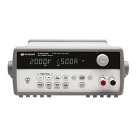
Keysight Technologies E3642A User's And Service Manual (237 pages)
Single Output DC Power Supplies
Brand:
Keysight Technologies
| Category:
Power Supply
| Size: 4.88 MB
Table of Contents
Safety Symbols
3
Safety Considerations
4
Safety and EMC Requirements
4
Safety Compliance
4
EMC Compliance
6
Environmental Conditions
7
Regulatory Markings
8
Waste Electrical and Electronic Equipment (WEEE) Directive
9
Product Category
9
Sales and Technical Support
9
Table of Contents
11
1 Getting Started
24
Introduction
24
Figure 1-1 Rear Output Terminals
27
Standard Shipped Items
28
Options
28
Table 1-1 E364Xa Options
28
Accessories
29
Table 1-2 E364Xa Accessories
29
Preparing the Power Supply
30
Checking the Power Supply
30
Connecting Power to the Power Supply
31
Table 1-3 E364Xa Power-Line Fuse
31
Checking the Output
32
Converting Line Voltage
34
Figure 1-2 Line Voltage Selector (Set for 115 Vac)
34
Adjusting the Carrying Handle
37
Rack-Mounting the Power Supply
38
Product at a Glance
40
Front Panel
40
Figure 1-3 Front Panel Outlook
40
Table 1-4 Front Panel Overview
41
Figure 1-4 Voltage and Current Limit Settings
42
Rear Panel
43
Figure 1-5 Rear Panel Outlook
43
Display Annunciators
44
Figure 1-6 Display Annunciators
44
Table 1-5 Rear Panel Overview
44
Table 1-6 Display Annunciators Overview
45
Output Connections
46
Current Ratings
46
Table 1-7 Wire Rating
46
Voltage Drops
47
Load Consideration
47
Remote Voltage Sensing Connections
48
Figure 1-7 Remote Voltage Sensing Connections
49
Figure 1-8 Local Sensing Connections
49
Multiple Loads
51
Operating the Power Supply
52
Cooling
52
Bench Operation
52
Cleaning
52
2 Operation and Features
53
Overview
54
Constant Voltage Operation
55
Front Panel Operation
55
Remote Interface Operation
57
Constant Current Operation
58
Front Panel Operation
58
Remote Interface Operation
60
Configuring the Remote Interface
61
GPIB Configuration
61
RS-232 Configuration
62
Storing and Recalling Operating States
63
Front Panel Operation
63
Remote Interface Operation
64
Programming the Overvoltage Protection
65
Front Panel Operation
65
Remote Interface Operation
67
Figure 2-1 Recommended Protection Circuit for Battery Charging
68
Figure 2-2 Recommended Connection to Prevent Voltage Overshoot
69
Disabling the Output
70
Disconnecting the Output Using an External Relay
71
System-Related Operations
72
State Storage
72
Self-Test
73
Error Conditions
74
Firmware Revision Query
74
SCPI Language Version
75
GPIB Interface Reference
76
RS-232 Interface Reference
77
RS-232 Configuration Overview
77
RS-232 Data Frame Format
77
Connection to a Computer or Terminal
78
Figure 2-3 DB-9 Serial Connection
78
RS-232 Trouble Shooting
79
Figure 2-4 DB-25 Serial Connection
79
Calibration
80
Calibration Security
80
To Unsecure for Calibration
81
Table 2-1 Factory-Setting Security Codes
81
To Secure against Calibration
82
To Change the Security Code
84
Calibration Count
85
Calibration Message
85
3 Remote Interface Reference
87
SCPI Command Summary
88
Output Setting and Measurement Commands
89
Triggering Commands
90
System-Related Commands
90
State Storage Commands
91
Calibration Commands
91
Interface Configuration Commands
91
Status Reporting Commands
92
IEEE-488.2 Common Commands
93
Introduction to the SCPI Language
94
Command Format Used in this Manual
95
Command Separators
96
Using the MIN and MAX Parameters
96
Querying Parameter Settings
97
SCPI Command Terminators
97
IEEE-488.2 Common Commands
98
SCPI Parameter Types
98
Simplified Programming Overview
100
Using the Apply Command
100
Using the Low-Level Commands
100
Reading a Query Response
101
Selecting a Trigger Source
101
Power Supply Programming Ranges
102
Using the Apply Command
104
Output Setting and Operation Commands
105
Triggering
110
Trigger Source
110
Triggering Commands
112
System-Related Commands
113
Table 3-3 Reset State of the Power Supply
116
State Storage Commands
117
Calibration Commands
119
Calibration Example
121
Interface Configuration Commands
123
SCPI Status Registers
124
What Is an Event Register
124
What Is an Enable Register
124
Figure 3-1 SCPI Status System
125
Questionable Status Register
126
Table 3-4 Bit Definitions - Questionable Status Register
126
Standard Event Register
127
Table 3-5 Bit Definitions - Standard Event Register
127
Status Byte Register
128
Table 3-6 Bit Definitions - Status Byte Summary Register
128
Using Service Request (SRQ) and Serial POLL
129
Using *STB? to Read the Status Byte
130
Using the Message Available Bit (MAV)
130
To Interrupt Your Bus Controller Using SRQ
130
Determining When a Command Sequence Is Completed
131
Using *OPC to Signal When Data Is in the Output Buffer
131
Status Reporting Commands
132
Halting an Output in Progress
135
SCPI Conformance Information
136
SCPI Confirmed Commands
136
Device Specific Commands
138
IEEE-488 Conformance Information
139
4 Error Messages
141
Overview
142
Front Panel Operation
142
Remote Interface Operation
143
Execution Error Messages
144
Table 4-1 Execution Error Messages
144
Self-Test Error Messages
150
Table 4-2 Self-Test Error Messages
150
Calibration Error Messages
153
Table 4-3 Calibration Error Messages
153
5 Application Programs
157
Overview
158
Example Program for C and C
159
Diode.C
159
Example Program for Excel 97
163
Declaration for Windows 3.1
167
Declaration for Windows 9.5/NT 4.0
167
6 Tutorial
169
Overview of the Power Supply Operation
170
Figure 6-1 Diagram of a Simple Series Power Supply
170
Figure 6-2 Block Diagram of the Power Supply Showing the Remote Interface Isolation
171
Output Characteristics
172
Figure 6-3 Ideal Constant Voltage Power Supply
172
Figure 6-4 Ideal Constant Current Power Supply
172
Figure 6-5 Output Characteristics
173
Unregulated State
174
Unwanted Signals
174
Figure 6-6 Simplified Diagram of Common Mode and Normal Mode Sources of Noise
175
Extending the Voltage and Current Range
176
Series Connections
176
Parallel Connections
176
Remote Programming
177
Figure 6-7 Speed of Response - Programming up (Full Load)
177
Figure 6-8 Speed of Response - Programming down
178
7 Characteristic and Specifications
180
Physical Characteristics
180
Figure 7-1 E364Xa Dimensions
180
Table 7-1 Physical Characteristics
180
Characteristic and
180
Environmental Characteristics
181
Figure 7-2 E364Xa Dimensions for Rack Mounting
181
Electrical Specifications
182
Table 7-2 Electrical Specifications
182
Supplemental Characteristics
184
Table 7-3 Supplemental Characteristics
184
8 Service and Maintenance
187
Overview
188
Operating Checklist
189
Types of Services Available
190
Standard Repair Service (Worldwide)
190
Repacking for Shipment
190
Electrostatic Discharge (ESD) Precautions
191
Surface Mount Repair
191
Replacing the Power-Line Fuse
191
Troubleshooting Hints
192
Unit Reports Errors 740 to 755
192
Unit Fails Self-Test
192
Bias Supplies Problems
192
Table 8-1 Bias Supplies Voltages
193
Table 8-2 Bias Supplies Voltages (Serial My53Xx6Xxx)
193
Self-Test Procedures
194
Power-On Self Test
194
Complete Self-Test
194
Table 8-3 Self-Test Error Messages
195
General Disassembly
196
Recommended Test Equipment
197
Table 8-4 Recommended Test Equipment
197
Test Considerations
199
Operation Verification and Performance Tests
200
Operation Verification Tests
200
Performance Tests
200
Measurement Techniques
201
Common Test Setup
201
Figure 8-1 Performance Verification Test Setup
201
Current-Monitoring Resistor
202
General Measurement Techniques
202
Figure 8-2 Front/ Rear Panel Terminal Connections
202
Electronic Load
203
Programming
203
Constant Voltage (CV) Verifications
204
Constant Voltage Test Setup
204
Voltage Programming and Readback Accuracy
204
Table 8-5 Verification Programming Values
204
CV Load Effect (Load Regulation)
206
CV Source Effect (Line Regulation)
207
CV PARD (Ripple and Noise)
208
Figure 8-3 Front/Rear Panel Terminal Connections for the Vrms
208
Figure 8-4 Transient Response Time
210
Load Transient Response Time
210
Constant Current (CC) Verification
211
Constant Current Test Setup
211
Current Programming and Readback Accuracy
211
CC Load Effect (Load Regulation)
213
CC Source Effect (Line Regulation)
214
CC PARD (Ripple and Noise)
215
Figure 8-5 CC PARD (Ripple and Noise) Connections
215
Common Mode Current Noise
217
Performance Test Record
218
Table 8-6 CV Performance Test Record
218
Table 8-7 CC Performance Test Record
219
Calibration Reference
221
Keysight Calibration Services
221
Calibration Interval
221
To Unsecure the Power Supply Without the Security Code
221
General Calibration or Adjustment Procedure
223
Table 8-8 Parameters for Calibration
223
Front Panel Voltage and Current Calibration
224
Calibration Record
228
Table 8-9 Calibration Record
228
Calibration Error Messages
230
Table 8-10 Calibration Error Messages
230
Component Locator Diagram
231
Component Locator Diagram for the Main Board Assembly - Bottom
232
Component Locator Diagram for the Front Panel
233
Component Locator Diagram for the Main Board Assembly - Top (Serial My53Xx6Xxx)
234
Component Locator Diagram for the Main Board Assembly - Bottom (Serial My53Xx6Xxx)
235
Advertisement
Advertisement
Related Products
Keysight Technologies E3646A
Keysight Technologies E3648A
Keysight Technologies E3647A
Keysight Technologies E3649A
Keysight Technologies E364xA Series
Keysight Technologies E3640A
Keysight Technologies E3641A
Keysight Technologies E3643A
Keysight Technologies E3644A
Keysight Technologies E3645A
Keysight Technologies Categories
Measuring Instruments
Test Equipment
Control Unit
Portable Generator
Power Supply
More Keysight Technologies Manuals
Login
Sign In
OR
Sign in with Facebook
Sign in with Google
Upload manual
Upload from disk
Upload from URL