Table of Contents
Advertisement
Advertisement
Table of Contents

Related Manuals for Cooper & Hunter CH-S07LX7


Summary of Contents for Cooper & Hunter CH-S07LX7
- Page 1 OWNER’S MANUAL Split Air Conditioner Prima Series M ODELS : CH-S07LX7 CH-S09LX7 CH-S12LX7 CH-S18LX7 CH-S24LX7 CH-S30LX7 For proper operation, please read and keep this manual carefully. Designed by Cooper&Hunter International Corporation, Oregon, USA www.cooperandhunter.com...
-
Page 2: Table Of Contents
Content Operation Notices Precautions......................1 Parts name ......................4 Screen Operation Guide Buttons on remote controller .................5 Introduction for buttons on remote controller ............6 Function introduction for combination buttons .............10 Replacement of batteries in remote controller .............11 Emergency operation . -
Page 3: Precautions
Precautions WARNING Operation and Maintenance ● This appliance can be used by children aged from 8 years and above and persons with reduced physical, sensory ormental capabilities or lack of experience and knowledge if they have been given supervision or instruction concerning use of the appliance in a safe way and understand the hazards involved. - Page 4 Precautions WARNING ● If the air conditioner operates under abnormal conditions, it may cause malfunction,electric shock or fire hazard. ● When turning on or turning off the unit by emergency operation switch, please press this switch with an insulating object other than metal. ●...
- Page 5 Precautions WARNING ● The air conditioner is the first class electric appliance. It must be properly grounding with specialized grounding device by a professional. Please make sure it is always grounded effectively, otherwise it may cause electric shock. ● The yellow-green wire in air conditioner is grounding wire, which can't be used for other purposes.
-
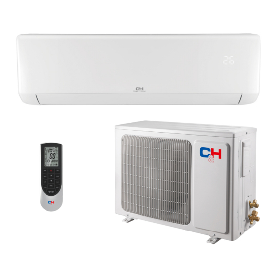
Page 6: Parts Name
Parts Name air inlet Indoor Unit panel aux.button horizontal louver air outlet temp. indicator power indicator receiver window (Display content or position may be different from above (Display content or position may be different from above remote controller graphics, please refer to actual products) graphics, please refer to actual products) Outdoor Unit air inlet... -
Page 7: Buttons On Remote Controller
Buttons on remote controller ON/OFF button MODE button FAN button SWING button TURBO button ▲/ button SLEEP button TEMP button I FEEL button LIGHT button CLOCK button TIMER ON / TIMER OFF button Introduction for icons on display screen Set fan speed I feel Send signal Operation mode... -
Page 8: Introduction For Buttons On Remote Controller
Introduction for buttons on remote controller Note: ● This is a general use remote controller, it could be used for the air conditioners with multifunction; For some function, which the model doesn't have, if press the corresponding button on the remote controller that the unit will keep the original running status. - Page 9 Introduction for buttons on remote controller temperature. Press "FAN" button to adjust fan speed. Press "SWING" button to adjust fan blowing angle. (Cooling only unit won’t receive heating mode signal. If setting heat mode with remote controller, press ON/OFF button can’t start up the unit).
- Page 10 Introduction for buttons on remote controller TURBO button Under COOL or HEAT mode, press this button to turn to quick COOL or quick HEAT mode. " " icon is displayed on remote controller. Press this button again to exit turbo function and " "...
- Page 11 Introduction for buttons on remote controller ● It’s defaulted to display set temperature when turning on the unit. There is no display in the remote controller. ● Only for the models whose indoor unit has dual-8 display. ● When selecting displaying of indoor or outdoor ambient temperature, indoor temperature indicator displays corresponding temperature and automatically turn to display set temperature after three or five seconds.
-
Page 12: Function Introduction For Combination Buttons
Introduction for buttons on remote controller TIMER ON setting will increase or decrease 1min. Hold "▲" or " " button, 2s later, the time will change quickly until reaching your required time. resumes displaying. Cancel TIMER ON: Under the condition that TIMER ON is started up, press "TIMER ON"... -
Page 13: Replacement Of Batteries In Remote Controller
Function introduction for combination buttons Combination of "MODE" and " " buttons: About switch between Fahrenheit and centigrade At unit OFF, press "MODE" and " " buttons simultaneously to switch between ℃ and ℉. Combination of "TEMP" and "TIMER" buttons: About Energy-saving Function (option) Press "TEMP"... -
Page 14: Clean And Maintenance
Clean and Maintenance WARNING ■ Turn off the air conditioner and disconnect the power before cleaning the air conditioner to avoid electric shock. ■ Do not wash the air conditioner with water to avoid electric shock. ■ Do not use volatile liquid to clean the air conditioner. Clean surface of indoor unit When the surface of indoor unit is dirty, it is recommended to use a soft dry cloth or wet cloth to wipe it. -
Page 15: Malfunction Analysis
Malfunction analysis General phenomenon analysis Please check below items before asking for maintenance. If the malfunction still Phenomenon Check items Solution ● Whether it's interfered severely ● Pull out the plug. Reinsert (such as static electricity, stable the plug after about 3min, and voltage)? then turn on the unit again. - Page 16 Malfunction analysis Phenomenon Check items Solution ● Power failure? ● Wait until power recovery. ● Is plug loose? ● Reinsert the plug. ● Air switch trips off or fuse is ● Ask professional to replace burnt out? air switch or fuse. Air condit- ●...
-
Page 17: Error Code
Malfunction analysis Phenomenon Check items Solution ● Whether there’s inter- ● Disconnect power, put back Air conditio- ference, such as thunder, power, and then turn on the ner operates wireless devices, etc. unit again. abnormally ● During defrosting under he- Outdoor ating mode, it may generate ●... -
Page 18: Installation Dimension Diagram
Installation dimension diagram Space to the wall At least 15cm At least 15cm Space to the wall Drainage pipe... -
Page 19: Tools For Installation
Tools for installation 1 Level meter 2 Screw driver 3 Impact drill 4 Drill head 5 Pipe expander 6 Torque wrench 7 Open-end wrench 8 Pipe cutter 9 Leakage detector 10 Vacuum pump 11 Pressure meter 12 Universal meter 13 Inner hexagon spanner 14 Measuring tape Note: ●... -
Page 20: Requirements For Electric Connection
Requirements for electric connection Safety precaution 1. Must follow the electric safety regulations when installing the unit. air switch. 3. Make sure the power supply matches with the requirement of air conditioner. Unstable power supply or incorrect wiring or malfunction. Please install proper power supply cables before using the air conditioner. -
Page 21: Installation Of Indoor Unit
Installation of indoor unit Step one: choosing installation location rm it with the client. Step two: install wall-mounting frame 1. Hang the wall-mounting frame on the wall; adjust it in horizontal position with the plastic expansion particles in the holes. 3. - Page 22 Installation of indoor unit Note: Indoor outdoor ● Pay attention to dust prevention and take relevant safety measures when opening the hole. ● The plastic expansion particles are Φ55 5-10° not provided and should be bought locally. Step four: outlet pipe 1.
- Page 23 Installation of indoor unit Step six: install drain hose 1. Connect the drain hose to the outlet pipe of indoor unit. drain hose outlet pipe 2. Bind the joint with tape. drain hose outlet pipe tape Note: drain hose ● Add insulating pipe in the indoor drain hose in order to prevent condensation.
- Page 24 Installation of indoor unit 4. Put wiring cover back and then tighten the screw. 5. Close the panel. Note: ● All wires of indoor unit and outdoor unit should be connected by a professional. for a new one. Avoid extending the wire by yourself. installation.
-
Page 25: Installation Of Outdoor Unit
Installation of indoor unit upper hook outdoor indoor wall pipe sealing gum lower hook of wall-mounting frame Note: ● Do not bend the drain hose too excessively in order to prevent blocking. Installation of outdoor unit (select it according to the actual installation situation) 1. - Page 26 Installation of outdoor unit Step three: connect indoor and outdoor pipes 1. Remove the screw on the right han- 3. Pretightening the union nut with dle of outdoor unit and then remove hand. the handle. pipe joint screw yellow- green union nut handle 2.
- Page 27 Installation of outdoor unit 2. Fix the power connection wire and signal control wire with wire clip (only for cooling and heating unit). Note: ● Never cut the power connection wire to prolong or shorten the distance. Step five: neaten the pipes 1.
-
Page 28: Vacuum Pumping
Vacuum pumping Use vacuum pump 1. Remove the valve caps on the liquid valve and gas liquid valve piezometer valve and the nut of refri- gas valve gerant charging vent. refrigerant charging 2. Connect the charging hose valve cap vent of piezometer to the refri- gerant charging vent of gas nut of refrigerant... -
Page 29: Check After Installation
Check after installation Items to be checked Possible malfunction The unit may drop, shake or emit noise. Have you done the refrigerant leakage test? (heating) capacity. It may cause condensation and water dripping. It may cause condensation and water Is water drained well? dripping. - Page 30 Designed by Cooper&Hunter International Corporation, Oregon, USA www.cooperandhunter.com E-mail: info@cooperandhunter.com * Co o o o o o per & & & Hu u u nter is co o o nstantly y y w w w o o o rk k k ing g g to o o im m m pro o o v v v e th h h eir pro o o d d d u u u cts, so o o th h h e inf f f o o o rm m m atio o o n in th h h is m m m anu u u al is su u u b b b j j j ect to o o ch h h ang g g e w w w ith h h o o o u u u t prio o o r no o o tice.
Need help?
Do you have a question about the CH-S07LX7 and is the answer not in the manual?
Questions and answers