Table of Contents
Advertisement
Quick Links
EN
For proper operation, please read and keep this manual carefully.
Designed by Cooper&Hunter International Corporation, Oregon, USA
OWNER'S MANUAL
Split Air Conditioner
VERITAS INVERTER Series
M ODELS :
www.cooperandhunter.com
CH-S0 7 FT XQ
CH-S09FT XQ (WI-FI)
CH-S12FTX Q (WI-FI)
CH-S18FTX Q (WI-FI)
CH-S24FTX Q (WI-FI)
Advertisement
Table of Contents

Related Manuals for Cooper & Hunter VERISTAS CH-S12FTXQ


Summary of Contents for Cooper & Hunter VERISTAS CH-S12FTXQ
- Page 1 OWNER’S MANUAL Split Air Conditioner VERITAS INVERTER Series M ODELS : CH-S0 7 FT XQ CH-S09FT XQ (WI-FI) CH-S12FTX Q (WI-FI) CH-S18FTX Q (WI-FI) CH-S24FTX Q (WI-FI) For proper operation, please read and keep this manual carefully. Designed by Cooper&Hunter International Corporation, Oregon, USA www.cooperandhunter.com...
-
Page 2: Table Of Contents
CONTENTS 1. IMPORTANT INFORMATIONS .......................... 1 2. COMPONENTS ..............................2 3. DISPLAY ................................2 4. REMOTE CONTROLLER DESCRIPTION ......................3 4.1. Description of functions of remote controller buttons ..................3 4.2. Name and functions of the display indicators ....................3 4.3. -
Page 3: Important Informations
1. IMPORTANT INFORMATIONS NORM: RISK: Electrocution from live components. Personal injury from Do not perform operations that involve opening the appliance. burns due to overheated components or wounds caused by sharp edges or protrusions. Do not perform operations that involve removing the appliance Electrocution from live components. -
Page 4: Components
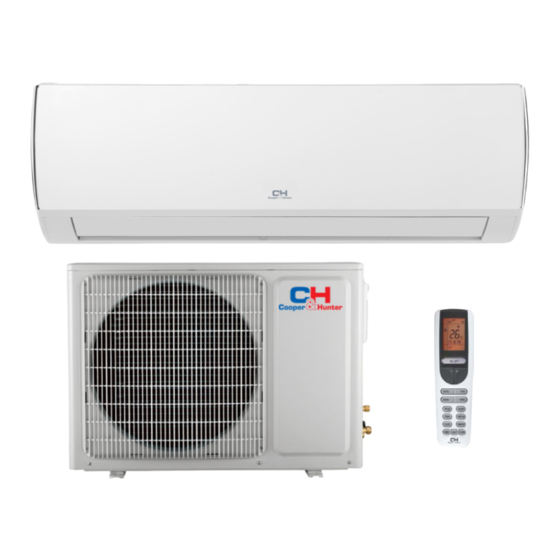
2. COMPONENTS INDOOR UNIT (1 ) (2 ) (3 ) (1) Air intake (2) Front panel (6 ) (3) Control panel (5 ) (4 ) (4) Air outlet (5) Air flow louver (1 2 ) (6) Air filter (8 ) (7) Air intake (8) Connecting pipe (9) Drain... -
Page 5: Remote Controller Description
4. REMOTE CONTROLLER DESCRIPTION 4.1. Description of functions of remote controller buttons ① button to turn the air conditioner on and off. ② MODE button to select the operating mode: AUTO “ ”, COOL “ ”, DRY “ ”, FAN “ ”, REMOTE CONTROLLER HEAT “... -
Page 6: How To Insert The Batteries
: Signal sent confirmation LED : IFEEL mode indicator : Fan Speed indicator : Temperature display indicator 4.3. How to insert the batteries Use two new alkaline type batteries with AAA 1,5V. ① Slide down the cover of the battery compartment. ②... - Page 7 1) Press the button to set swing up and down angle, which circularly changes as below: Note: This remoter is universal. If any command is sent out, the unit will carry out the command as indicates the guide louver swings as: 2) Press the button to set left and right swig angle, which circularly changes as below (not available)
-
Page 8: Manual Operation
time for appliance on. ♦ Press the ''▲'' / ''▼'' button once to increase or decrease the time setting by 1 minute. ♦ Press the button ''▲'' / ''▼'' for 2 seconds to increase/decrease the time setting by 10 minutes. Note: If you don't set the time in 10 seconds after you press TIMER ON button, the remote controller will exit the TIMER ON mode automatically. -
Page 9: Maintenance
5. MAINTENANCE WARNING It is necessary to stop the air conditioner and disconnect the power supply before Household cleaning. Drain Cleaner Cleaning the indoor unit and remote controller CAUTIONS ● Use a dry cloth to wipe the indoor unit and remote controller. ●... -
Page 10: Operations And Performances
Do not use water to clean inside the air conditioner. Exposure to water can destroy the insulation, leading to possible electric shock. When cleaning the unit, first make sure that the power and circuit breaker are turned off. 6. -
Page 11: Troubles And Causes
9. Auto-restart function Power failure during operation will stop the unit completely. For the unit without Auto-restart feature, when the power restores, the OPERATION indicator on the indoor unit starts flashing. To restart the operation, push the button on the remote controller. For the unit with Auto-restart feature, when the power restores, the unit restarts automatically with all the previous settings preserved by the memory function. -
Page 12: Installation
8. INSTALLATION Indoor unit ● Do not expose the indoor unit to heat or steam. ● Select a place where there are no obstacles in front or around the unit. ● Make sure that condensation drainage can be conveniently routed away. ●... - Page 13 Rooftop installation: ● If the outdoor unit is installed on a roof structure, be sure to level the unit. Ensure the structure and anchoring method are adequate for the unit location. ● Consult local codes regarding rooftop mounting. ● If the outdoor unit is installed on roof structures or external walls, this may result in excessive noise and vibration, and may also be classed as a non-serviceable installation.
- Page 14 Indoor unit installation 1. Pass the piping through the hole in the wall. 2. Put the upper claw at the back of the indoor unit on the upper hook of the installation plate, move the indoor unit from side to side to see that it is securely hooked.
- Page 15 Wiring connections Connect the cable to the indoor unit 1. Indoor/Outdoor connection cable should be H07RN-F type. Front panel Terminal 2. Lift the indoor unit panel up and remove the screw, then remove the window cover 3. Connect cables according to their marks to terminals. 4.
- Page 16 Refrigerant piping connection 1. Flaring work Main cause for refrigerant leakage is due to defect in the flaring work. Carry out correct flaring work using the following procedure: A: Cut the pipes and the cable. 1. Use the piping kit accessory or pipes purchased locally. 2.
- Page 17 Air purging Air and moisture in the refrigerant system have undesirable effects as indicated below: ● Pressure in the system rises. Indoor unit ● Operating current rises. ● Cooling or heating efficiency drops. Outdoor unit ● Moisture in the refrigerant circuit may freeze and block capillary tubing. ●...
-
Page 18: Test Operation
5. After the evacuation is complete, fully close the handle Lo of the manifold valve and stop the operation of the vacuum pump. Make evacuation for 15 minutes or more and check that the compound meter indicates -76cmHg (1x10⁵Pa). 6. Turn the stem of the packed valve B about 45° counter clockwise for 6-7 seconds after the gas coming out, and then tighten the flare nut again. - Page 19 Designed by Cooper&Hunter International Corporation, Oregon, USA www.cooperandhunter.com E-mail: info@cooperandhunter.com * Cooper&Hunter постоянно работает над улучшением своей продукции, поэтому информация приведенная в данном руководстве, может быть изменена без предварительного уведомления потребителей. 66160000078...
Need help?
Do you have a question about the VERISTAS CH-S12FTXQ and is the answer not in the manual?
Questions and answers