
Subscribe to Our Youtube Channel
Related Manuals for METREL MI 3295


Summary of Contents for METREL MI 3295
- Page 1 Step Contact Voltage Measuring System MI 3295 Instruction manual Version 2.1.1, Code no. 20 752 071...
- Page 2 The trade names Metrel , Smartec , Eurotest , Auto Sequence are trademarks registered in Europe and other countries. No part of this publication may be reproduced or utilized in any form or by any means without permission in writing from METREL.
-
Page 3: Table Of Contents
MI 3295 Step Contact Voltage Measuring System Table of contents Table of content Preface ........................5 Safety and operational considerations ..............6 Warnings and notes....................6 Battery and charging of MI 3295M ................ 6 2.2.1 New battery cells or cells unused for a longer period ............. 8 Standards applied .................... - Page 4 MI 3295 Step Contact Voltage Measuring System Table of contents 7.2.2 Synchronization before the test (recommended) ............29 7.2.3 Step voltage and Contact/Touch voltage measurements ..........30 7.2.4 Potential.......................... 31 7.2.5 Synchronization after the test (recommended) ............. 32 Current measurement ..................33 Earth resistance ....................
-
Page 5: Preface
Current The instrument is equipped with all the necessary accessory for comfortable testing. The PC SW Metrel ES Manager enables uploading structure, downloading of results, storing of results and making test reports. Some measuring system highlights: Graphic LCD displays on Meter and Station. -
Page 6: Safety And Operational Considerations
MI 3295 Step Contact Voltage Measuring System Safety and operational considerations 2 Safety and operational considerations 2.1 Warnings and notes In order to reach high level of operator’s safety while carrying out various tests and measurements using the Step Contact Voltage Measuring System, as well as to keep the equipment undamaged, it is necessary to consider the following general warnings: Warning on the instrument means »Read the Instruction manual with... - Page 7 MI 3295 Step Contact Voltage Measuring System Safety and operational considerations Figure 2.1: Discharged battery indication The battery is charged whenever the power supply adapter is connected to the instrument. Internal circuit controls charging assuring maximum battery lifetime. The power supply socket polarity is shown in Figure 2.2.
-
Page 8: New Battery Cells Or Cells Unused For A Longer Period
/ discharged. This information is provided in the technical specification from battery manufacturer. 2.3 Standards applied The Step Contact Voltage Measuring System (MI 3295) is manufactured and tested according to the following regulations, listed below. Electromagnetic compatibility (EMC) IEC/ EN 61326-1... - Page 9 MI 3295 Step Contact Voltage Measuring System Safety and operational considerations Safety (LVD) IEC/ EN 61010-1 Safety requirements for electrical equipment for measurement, control, and laboratory use – Part 1: General requirements IEC/ EN 61010-2-030 Safety requirements for electrical equipment for measurement, control and laboratory use –...
-
Page 10: Instrument Description Mi 3295M Meter
MI 3295 Step Contact Voltage Measuring System Instrument description 3295 M Meter 3 Instrument description MI 3295M Meter 3.1 Front panel Figure 3.1: Front panel Legend: 1 LCD LCD display with backlight 2 ESC Returns to previous menu 3 MEM... -
Page 11: Connector Panel
MI 3295 Step Contact Voltage Measuring System Instrument description 3295M Meter 3.2 Connector panel Figure 3.2: Connector panel Legend: Charger socket USB communication port Communication with PC USB (1.1) port PS/2 communication port RS232 serial communication port Current clamp inputs... - Page 12 MI 3295 Step Contact Voltage Measuring System Instrument description 3295M Meter Figure 3.4: Battery compartment Legend: Serial number label Battery cells (size AA)
-
Page 13: Instrument Description Mi 3295S Station
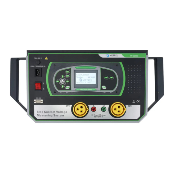
MI 3295 Step Contact Voltage Measuring System Instrument description 3295S Station 4 Instrument description MI 3295S Station 4.1 Front panel Figure 4.1: Front panel Legend: Fuse and voltage Supply voltage range selector with mains fuses. See selector cover chapter 9.1 Fuse replacement and range selection for more information. -
Page 14: Instrument Set And Accessories
MI 3295 Step Contact Voltage Measuring System Instrument description 3295S Station 4.2 Instrument set and accessories 4.2.1 Standard set Instrument MI 3295S 1 pc Instrument MI 3295M 1 pc Mains cable 1 pc Step voltage probe (25 kg) or Step voltage plates... -
Page 15: Mi 3295M Meter Operation
MI 3295 Step Contact Voltage Measuring System MI 3295M Meter operation 5 MI 3295M Meter operation 5.1 Organization of display Function name Result field Test parameter field Figure 5.1: Typical function display Message field 5.1.1 Battery indication The battery indication indicates the charge condition of battery and connection of external charger. -
Page 16: Backlight And Contrast Adjustments
MI 3295 Step Contact Voltage Measuring System MI 3295M Meter operation 5.2 Backlight and contrast adjustments With the BACKLIGHT key backlight and contrast can be adjusted. Figure 5.2: Contrast adjustment menu BACKLIGHT key: Click Toggle backlight intensity level. Lock high intensity backlight level until power is turned off or the Keep pressed for 1 s key is pressed again. -
Page 17: Language
MI 3295 Step Contact Voltage Measuring System MI 3295M Meter operation 5.4.1 Language Language can be set in the SELECT LANGUAGE menu. Figure 5.4: Language selection Keys: Cursor UP / DOWN Selects language. TEST Confirms selected language. Returns to Settings main menu. -
Page 18: Date And Time
MI 3295 Step Contact Voltage Measuring System MI 3295M Meter operation Function Parameter Default value Limit Contact/Touch Voltage Iset 10.0 A Step Voltage Iflt 1.0 kA Rinp 1.0 kΩ Ulim Potential Iset 10.0 A Iflt 10 A Step 1.0 m 0°... - Page 19 MI 3295 Step Contact Voltage Measuring System MI 3295M Meter operation Synchronized data: Station’s time and date will be uploaded to the Meter. BEFORE TESTS Value of generator current will be uploaded to the Meter (if current generator is on).
-
Page 20: Mi 3295S Station Operation
MI 3295 Step Contact Voltage Measuring System MI 3295S Station operation 6 MI 3295S Station operation 6.1 Organization of displays Function name Result & Sub-result field Figure 6.1: Typical display in earth Message field resistance function Function name Test parameter field 2.4m... -
Page 21: Help Screens
MI 3295 Step Contact Voltage Measuring System MI 3295S Station operation Date / time was changed in the Station and consequentially the synchronization between Station and Meter is lost. The Current logger must be cleared. Before clearing it its content can be downloaded to the Meter. -
Page 22: Settings
MI 3295 Step Contact Voltage Measuring System MI 3295S Station operation 6.6 Settings Different instrument options can be set in the SETTINGS menu. Options are: Selection of language Setting the instrument to initial values Setting the output power of the ... -
Page 23: Date And Time
MI 3295 Step Contact Voltage Measuring System MI 3295S Station operation 6.6.3 Date and time Same as in MI 3295M – see chapter 5.4.4 Date and time. 6.6.4 Output power range In this menu the power of the current generator can be set. -
Page 24: Measurements
MI 3295 Step Contact Voltage Measuring System Measurements 7 Measurements 7.1 Theory of measurements 7.1.1 General on earthing An earthing electrode / grid depleted into ground has a certain resistance, depending on its size, surface (oxides on the metal surface) and the soil resistivity around the electrode. -
Page 25: General On Specific Earth Resistance
MI 3295 Step Contact Voltage Measuring System Measurements For a longer exposure the touch voltages must stay below 50 V. 7.1.2 General on specific earth resistance The specific earth resistance (soil resistivity) is measured to determine the characteristic of the soil. The measurement is carried out in order to assure more accurate calculation of earthing systems e.g. - Page 26 For the earthing resistance test a voltage and current probe (serves as auxiliary earth) are used. Because of the voltage funnel it is important that the test electrodes are placed correctly. More information about measuring earth resistance can be found in the METREL handbook: Guide for testing and verification of low voltage installations.
- Page 27 By increasing the distances ‘a’ a deeper layer of ground material is measured. More information about measuring earth resistance can be found in the METREL handbook: Guide for testing and verification of low voltage installations. Figure 7.5: Specific earth resistance measurement...
-
Page 28: Step Voltage, Contact/Touch Voltage And Potential
MI 3295 Step Contact Voltage Measuring System Measurements Current measurements Current measurement is intended for measurement of AC currents (leakage currents, load currents, noise currents) using the iron current clamps or flex clamps. Figure 7.7: TRMS, 50 Hz, 60 Hz current measurement example: Iron clamp (left) and Flex clamps (right) Figure 7.8: Current measurement example –... -
Page 29: Synchronization Before The Test (Recommended)
MI 3295 Step Contact Voltage Measuring System Measurements Connections for Step voltage, Contact/Touch voltage and Potential measurement For connections of the Station see Figure 7.2, Figure 7.3 and Figure 7.6. Figure 7.10: Example of the display during generation of current Note: The output power is set automatically to its available maximum. -
Page 30: Step Voltage And Contact/Touch Voltage Measurements
MI 3295 Step Contact Voltage Measuring System Measurements changing during the test the I parameter must be adjusted manually. The measurement results cannot be corrected after the measurement. 7.2.3 Step voltage and Contact/Touch voltage measurements While the Station injects the measuring current into earth the Step or Contact/Touch voltage tests with the Meter can be carried out. -
Page 31: Potential
MI 3295 Step Contact Voltage Measuring System Measurements Note: For dry soil or concrete floor, a damp cloth or a film of water should be placed between the probe and the floor. It is possible to work with more Meters at the same time. -
Page 32: Synchronization After The Test (Recommended)
MI 3295 Step Contact Voltage Measuring System Measurements Connections for Potential measurement For connections see Figure 7.6. Figure 7.15: Example of Potential measurement results Displayed results for Potential measurements: Us ... calculated potential Um...measured potential d ....Distance between earthing rod (E) and measurement point... -
Page 33: Current Measurement
MI 3295 Step Contact Voltage Measuring System Measurements Connections for synchronization For connection of the instruments see Figure 7.11. Figure 7.18: Examples of synchronization screens NOT SYNCHRONIZED: number of non-synchronized results. Note: Synchronization of Step voltage, Contact /Touch voltage and Potential results can ... -
Page 34: Earth Resistance
MI 3295 Step Contact Voltage Measuring System Measurements Connections for current measurement For connections see Error! Reference source not found. and Error! Reference source not found.. Figure 7.20: Examples of current measurement results Displayed result for current measurement: I....current 7.4 Earth resistance... -
Page 35: Specific Earth Resistance Measurement
MI 3295 Step Contact Voltage Measuring System Measurements Notes: High resistance of S and H probes could influence the measurement results. In this case the ‘Probe’ warnings are displayed. High noise currents and voltages in earth could influence the measurement results. -
Page 36: Downloading Earth Results To The Meter
MI 3295 Step Contact Voltage Measuring System Measurements 7.4.3 Downloading Earth results to the Meter To view stored earth resistance or specific earth resistance results on PC they must be downloaded to the Meter first. Connect Meter to the Station with the RS232 cable. See Figure 7.11. -
Page 37: Data Handling
The main advantages of this system are: Test results can be organized and grouped in a structured manner. Data structure can be uploaded from the Metrel ES Manager to the Meter and with synchronization also to the Station. -
Page 38: Storing Test Results
MI 3295 Step Contact Voltage Measuring System Data handling Measurement field No. of measurements in selected location. No. of measurements in selected location. [No. of measurements in selected location and its sub locations]. No. of selected test result / No. of all stored test results in selected location. -
Page 39: Clearing Stored Data
MI 3295 Step Contact Voltage Measuring System Data handling Keys in recall memory menu (data structure field selected): Cursor UP / DOWN Selects the location element (Project / Object / Test point). Cursor LEFT / RIGHT Selects number of selected location element (1 to 199). - Page 40 MI 3295 Step Contact Voltage Measuring System Data handling Figure 8.8: Clear measurements menu (data structure field selected) Keys in delete results menu (data structure field selected): Cursor UP / DOWN Selects location element (Project / Object / Test point).
-
Page 41: Current Logger
MI 3295 Step Contact Voltage Measuring System Data handling 8.2 Current Logger If the Meter and Station are synchronized the values of generated currents are stored (together with time and date) in a separated part of the Station’s memory. See chapters 5.4.5 Synchronization and 7.2.5 Synchronization after the test (recommended) for more... -
Page 42: Communication
The PC and the instrument will automatically recognize each other. The instrument is prepared to communicate with the PC. Metrel ES Manager is a PC software running on Windows 7, Windows 8, Windows 8.1 and Windows 10. -
Page 43: Maintenance
MI 3295 Step Contact Voltage Measuring System Maintenance 9 Maintenance Unauthorized persons are not allowed to open the instruments. There are no user replaceable components inside the instrument, except the battery under rear cover of Meter (MI 3295M). See chapter 2.2 Battery and charging of MI 3295M. -
Page 44: Cleaning
MI 3295 Step Contact Voltage Measuring System Maintenance Fuse replacement Figure 9.2: Fuse replacement procedure There are two fuses on the front cover of the MI 3295S Station: Fuse: 2 x T 6.3 A / 250 V, (5 mm 20 mm) ... -
Page 45: Periodic Calibration
MI 3295 Step Contact Voltage Measuring System Maintenance 9.3 Periodic calibration It is essential that the test instrument is regularly calibrated in order that the technical specification listed in this manual is guaranteed. We recommend an annual calibration. Only an authorized technical person can do the calibration. Please contact your dealer for further information. -
Page 46: Technical Specifications
MI 3295 Step Contact Voltage Measuring System Technical specifications Technical specifications 10.1 Step voltage, Contact/Touch voltage (MI 3295M) Measuring range U Resolution Accuracy 0.01 … 19.99 mV 0.01 mV 20.0 … 199.9 mV 0.1 mV (2 % of reading + 2 dig) 200 …... -
Page 47: Specific Earth Resistance (Mi 3295S)
MI 3295 Step Contact Voltage Measuring System Technical specifications Test signal frequency ........55 Hz Influence of probe resistance: ≤ (10 % of reading + 10 digits) = (10 + 100 R) or 2 k (whichever is lower) (Rc, Rp) Automatic test of probe resistance.. -
Page 48: Current (Mi 3295M)
MI 3295 Step Contact Voltage Measuring System Technical specifications (selectable) ..1 A ... 200 kA fault Step ......[0.5 m … 5.0 m] or [1 ft … 17 ft] Input resistance: 1 MΩ Noise cancelation: DSP filtering 55 Hz, 64 dB rejection of 50 (60) Hz noise... -
Page 49: General Data
MI 3295 Step Contact Voltage Measuring System Technical specifications Noise cancelation ± 5 Hz (50 Hz, 55 Hz and 60 Hz mode) ..DSP filtering, - 64 dB @ f MODE Measuring refresh rate ..... typical 2.6 s (50 Hz, 55 Hz and 60 Hz mode) typical 1.5 s (TRMS mode) - Page 50 MI 3295 Step Contact Voltage Measuring System Technical specifications Charger socket input voltage ....12 V (10 %) Charger socket input current ....400 mA max Battery charging current ......250 mA (internally regulated) Measuring category ........ CAT IV / 50 V Protection classification ......
Need help?
Do you have a question about the MI 3295 and is the answer not in the manual?
Questions and answers