
Related Manuals for Dynapac PL 500/20 S


Summary of Contents for Dynapac PL 500/20 S
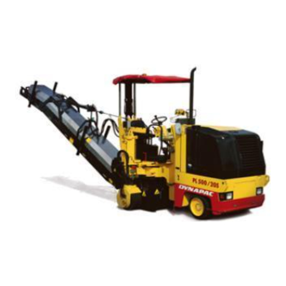
- Page 1 Operation & Maintenance Cold planer PL 500/20 S Keep for later use in document compartment Order no. for this handbook: 900 98 12 71 02-0407 Valid from serial number: 503.173 ......
- Page 2 VALUE QUALITY THE ORIGINAL SPARE PARTS Y our authorised Dynapac dealer:...
- Page 3 Preface If the machines are to be operated safely, the information provided in these Operating Instructions will be required. The information is provided in a concise, clearly struc- tured form. The individual chapters are arranged in alphabetical order. Every chapter starts on page 1.
- Page 4 These Operating Instructions must always be stored in a convenient location on the machine. They are valid in conjunction with the Dynapac safety manual, the informa- tion on intended usage and the supplementary operator’s instructions required on the basis of existing national or regional specifications regarding technical regulations, accident prevention and environmental protection.
-
Page 5: Table Of Contents
Table of Contents Correct use and application ........... 1 Vehicle description ..............1 Application ....................1 Descriptions of assemblies and functions ..........2 Vehicle ....................... 3 Construction ................... 3 Safety devices .................... 5 Emergency-stop button ................5 Horn ....................... 5 Headlights, flashers, rotary beacons ............. - Page 6 Operation ................. 1 Safety regulations ..................1 Controls ...................... 2 Operating panel ..................2 Sockets and interfaces on the operating panel ........32 Other controls ..................34 Controls at operator’s control station ............34 Setting up the control panel ..............34 Driver’s seat ..................
- Page 7 Actual value calibration ................73 Digi-Slope sensor (lateral slope sensor) ..........73 Initial situation for actual value calibration ........... 73 Other tasks ..................73 Height sensors (to correct the actual value to the value displayed) ..75 Operation ....................76 Preparing for operation ................
- Page 8 Set-up and modification ............1 Special notes on safety ................1 Planing without upper conveyor / Preparation for transport ....... 2 Dismantling the upper conveyor ..............2 Maintenance ................1 Notes regarding safety ................1 Liability is rendered null and void if non-genuine spares or wearing parts or incorrect fuel substances are used.
- Page 9 Loading unit ..................... 42 Belt tension ..................42 Steel cables ..................44 Rubber funnel gasket at transfer point and rubber seals / guides ..44 Water system ................... 45 Water tank ................... 45 Remove water tank ................46 Water filter ................... 47 Spray nozzles ..................
-
Page 11: A Correct Use And Application
A Correct use and application The Dynapac „Guideline for the intended and correct usage of cold planers“ falls with- in the scope of supply of this machine. The guidelines are part of the present operat- ing instructions and must always be heeded. National regulations are fully applicable. - Page 12 Technical modifications, attachments and conversions: The cold planer may on- ly be operated with the extension parts, optional equipment and accessories, protec- tion and safety devices authorised by the manufacturer as well as the setting values specified by the manufacturer. Autonomous changes to assemblies, their removal or replacement with other unauthorised parts and any attempt to take these out of serv- ice either completely or partially render null and void the manufacturer’s liability for any resultant damage.
-
Page 13: B Vehicle Description
B Vehicle description Application The DYNAPAC PL 500/20 S cold planer is a compact and very manoeuvrable cold planer with all-wheel drive and, depending on equipment standard, can be fitted with either three or four drive wheels. This cold planer was designed for tasks such as the partial removal of asphalt and concrete and for preparatory work in pipeline and cable-laying operations. -
Page 14: Descriptions Of Assemblies And Functions
Descriptions of assemblies and functions PL500_compl.wmf Item Designation Frame Operator’s control station Driver’s seat Drive wheel Chassis leg Swivel-mounted chassis leg Milling depth indicator Water tank Water spraying system Weather protecting sun roof ( Upper conveyor... -
Page 15: Vehicle
Vehicle Construction Frame and assembly: Robust, distortion-resistant steel welded design with useful brackets for supporting the assemblies, units, attachments and tanks. All parts can be easily accessed for maintenance and repair work. Operator’s control station: The operator’s control station, conveniently located at the rear of the machine affording good all-round visibility, can be reached via a ladder and is equipped with a driver’s seat on the right-hand side. - Page 16 Milling depth control: milling depth control is performed hydraulically, and separate- ly for each chassis leg. To the left and right sides of the operator’s control station are two clearly legible mill- ing depth indicators. Traction unit, steering system, travel drive, brake: The suspension for both front wheels takes the form of a parallel rocker arm arrangement which delivers an opti- mum locating surface at all times.
-
Page 17: Safety Devices
Safety devices Safe operation is only possible if the operating and safety equipment works perfectly, and that guards are properly fitted. The function of these devices must be checked regularly (refer to Chapter D, Section „Checklists for the machine operator“). Emergency-stop button - On the control panel The engine, drives and steering sys-... -
Page 18: Headlights, Flashers, Rotary Beacons
Headlights, flashers, rotary beacons Lights for illuminating different operating areas and for indicating danger areas and/or dangerous situations are located at various machine positions. The machine has two contacts which can be fitted to the headlights or to the rotary beacons. The headlights or rotary beacons are en- gaged using their respective switches on the control panel. -
Page 19: Limit Switch On Upper Conveyor
Limit switch on upper conveyor A limit switch on the frame of the upper conveyor prevents unfavourable load levels arising from excessive raising ac- tion. Limit_PL600.wmf... -
Page 20: Technical Data, Standard Version
Technical data, standard version Dimensions PL500_measure_side_long.wmf, PL500_measure_top_long.wmf... - Page 21 PL500_measure_side_short.wmf, PL500_measure_top_short.wmf...
-
Page 22: Weights
Weights Upper Upper conveyor conveyor long short Unladen weight 8,550 8,050 Operating weight 8,850 8,350 Ballast weight, total max. 9,100 8,600 Performance data Transport speed 0 - 6 km/h Working speed 0 - 30 m/min Milling width Milling depth 0 - 200 Spacing Cutting diameter Number of milling tools - System KPF201... -
Page 23: Engine
Engine Make/type Cummins QSB 4.5-30-T-C110 Model 4-cylinder diesel engine (water-cooled) Power (in accordance with DIN 82 kw / 110 hp / 112 hp (at 2100 1/min) 6270) Capacity 4510 cm Fuel consumption, full load 23.6 l/h Fuel consumption, 2/3 load 15.8 l/h Fuel tank filling volume approx. -
Page 24: Water System
Water system 4 units Spray nozzles Water tank - filling volume approx. 400 Loading system Belt width, upper conveyor Belt speed approx. 4 Loading capacity (theoretical) approx. 80 Electrical system On-board voltage 24 V Batteries 2 x 12 V, 170 Ah Generator 24 V / 100 A B 12... -
Page 25: Identification Points And Type Plates
Identification points and type plates Type plate and vehicle identification number Side500_compl.wmf/Iso500_complback.wmf Item Designation Position Vehicle frame, recess for swivel- Type plate mounted chassis leg. Vehicle Identification Number Vehicle frame at rear, right-hand side (VIN) of engine compartment flap. B 13... -
Page 26: Type Plate, Machine
Type plate, machine Fertiger3.tif Item Designation Planer type Year of construction Serial number of machine model Maximum permitted operating weight in kg Maximum permitted axle load at front in kg (CE) Maximum permitted axle load at rear in kg (CE) Rated performance in kW Product identification number (PIN) B 14... -
Page 27: Identification Points
Identification points B 15... - Page 28 B 16...
- Page 29 Item Spare parts no. Comments 956.05.20.07 990.00.02.05 956.05.20.03 956.05.30.03 990.00.02.17 956.04.53.00 956.05.20.08 Left and right on radiator 956.05.20.02 956.05.20.09 Beside the batteries 956.05.30.02 990.00.02.15 On filler neck for diesel fuel 956.05.30.39 956.04.49.00 956.05.20.10 956.05.20.11 956.05.20.05 956.05.20.04 956.04.31.00 956.05.10.04 990.00.02.21 990.05.20.18 On both sides of the loading belt cover 956.05.20.19 956.05.20.20...
-
Page 30: En Standards
EN standards Continuous sound pressure level Ear protectors must be worn when operating this machine. The emission value at the ear of the driver varies depending on the materials used for paving and may even rise above 85 dB (A). If no ear protection devices are used, hearing can be impaired. The measurements of noise emissions of the cold planer have been taken in accord- ance with the draft of ENV 500-6, dated March 1997 and ISO 4872 under free-field conditions. -
Page 31: Vibration Acting On The Entire Body
Vibration acting on the entire body When the machine is used properly, the weighted effective acceleration values at the driver’s seat of a = 0.5 m/s according to prEN 1032-1995 are not exceeded. Vibrations acting on hands and arms When the machine is used properly, the weighted effective acceleration values at the driver’s seat of a = 2.5 m/s according to prEN 1033-1995 are not exceeded. -
Page 33: C Transport
C Transport Safety regulations for transport There is a risk of accident if the machine is prepared incorrectly and transportation is conducted incorrectly Prepare the machine ensuring that all components are secured and cannot come loose. Dismantle all protruding and removable components and/or fit them so that they do not represent a hazard! Lower the machine until the bit tips on the milling drum are approx. -
Page 34: Fix Points
Fix points Side500_compl.wmf There are two fix points (1) on each side of the machine frame, at the front and back. The machine should be fastened to these points during transport on the transport ve- hicle. The machine is to be fixed to the transporter using sufficiently sized shackles (chains) and secured so that it cannot tilt, slide or fall off. -
Page 35: Transportation On Low-Bed Trailers
Transportation on low-bed trailers When transporting the machine on trailers, the load dimensions and weights should be taken into account when selecting and using appropriate tractor vehicles and transporters in accordance with the road traffic and registration authorities. Approach ramps and tracks of the trailer should be coated with a slip-free material. There must be sufficient possible attachment points on the trailer. -
Page 36: Normal On-Road Travel
Normal on-road travel The machine is intended for operation and use within self-contained construction sites. If the loading or discharge section of the machine is outside the enclosed construction site, or if the machine needs to be driven from one section of a site to another, a sec- ond person must accompany the machine for that journey. -
Page 37: Loading By Crane
Loading by crane In the event of breakdown, should it no longer be possible for the machine to be towed or if it cannot be loaded in any other way, there is also the possibility of raising it by crane. Use only lifting gear that can bear the load. -
Page 38: Towing
Towing Comply with all specifications and introduce all requisite safety measures required for the towing of construction equipment. The tractor vehicle must be such that it can still hold the machine when travelling downhill. Only use authorised towbars! Do not disengage travel drive and release brake until the machine has been properly secured to prevent accidental rolling away, or is already properly connected to the towing vehicle. -
Page 39: Safely Parking The Vehicle
Safely parking the vehicle When parking on publicly accessible ar- eas, the machine should be secured to ensure that unauthorised persons and children cannot cause any damage to it. The machine should be parked on level ground. - Lower the machine evenly until the milling drum is almost in contact with the ground. -
Page 41: D Operation
D Operation Safety regulations Injury or death can result whenever the engine, travel drive, milling drum, conveyor or lifting units are engaged. When operating the machine, therefore maintain strict compliance with the sections of these operating instructions and the safety specifications dealing with personal conduct. -
Page 42: Controls
Controls Operating panel Panelkompl_ALL_V3.bmp/Verriegel_Lenk.cdr/Panel4_V2_Iso.bmp... - Page 43 Item Designation Brief description The entire steering unit can be adjusted in the inclined plane. Safeguard - Open both interlocks and swivel steering unit up- steering unit wards or downwards using both hands. - Close safeguard again once desired position has been reached.
- Page 44 Panel3_V2.bmp...
- Page 45 Item Designation Brief description Steering action is transmitted hydraulically to the front wheel or wheels. Steering wheel To allow for safe handling, the steering wheel is equipped with a steering knob. Switch positions: P: Active lighting + hazard flasher can be engaged 0: Ignition OFF 1: Ignition ON 2: Starter function...
- Page 46 28 29 30 Panel2_500_1000.bmp...
- Page 47 Item Designation Brief description In the case of an emergency (danger to persons, pos- sible collision etc.), press in the button! The engine, drive units and steering are disen- gaged whenever the EMERGENCY STOP button EMERGENCY is pressed. STOP button To restart the engine, all EMERGENCY STOP but- tons must be raised.
- Page 48 28 29 30 Panel2_500_1000.bmp...
- Page 49 Item Designation Brief description To regulate pressure for scraper relief To set the pressure at which the moldboard slides over the milling lane. Pressure regula- The pressure setting determines the extent to tor relief pressure which the milling lane is cleared of milling de- Moldboard bris.
- Page 50 28 29 30 Panel2_500_1000.bmp D 10...
- Page 51 Item Designation Brief description Two switch positions can be selected: Hare: Transport speed Tortoise: Working speed When changing from working speed to trans- portation speed, the milling drum transmission Travel drive is automatically disengaged. fast / slow This operating mode can only be changed over once the machine is stationary and the drive le- ver is in centre position! To swivel the right-hand chassis leg in and out, e.g.
- Page 52 28 29 30 Panel2_500_1000.bmp D 12...
- Page 53 Item Designation Brief description This switches the milling drum transmission on or off. Top shift position: milling drum transmission en- gaged, Bottom shift position: milling drum transmission en- gaged. Milling drum Before the milling drum transmission is en- transmission ON / gaged, check to ensure that the machine is not lowered to such a point that the milling drum makes contact with the substrate.
- Page 54 28 29 30 Panel2_500_1000.bmp D 14...
- Page 55 Item Designation Brief description Two switch positions can be selected: 0: Moldboard blocked - remains in the desired po- sition Selector switch : moldboard in floating position Scraper During milling operations, the moldboard should (moldboard) always be in float position. Under certain work- ing conditions, it is however possible for the scraper to dig into the substrate.
- Page 56 28 29 30 Panel2_500_1000.bmp D 16...
- Page 57 Item Designation Brief description Two switch positions can be selected: Top shift position: Fast raising and lowering speeds Raising and low- (e.g. for inching operation) ering speed Bottom shift position: Normal raising and lowering speed (e.g. for „initial surface scraping and for mill- ing operation) Three switch positions can be selected: 0: Levelling OFF...
- Page 58 Panel1_500_1000_V2.bmp/Panel_Leucht_500_1000_V2.bmp D 18...
- Page 59 Item Designation Brief description Always heed the fuel gauge. Fuel gauge Do not completely empty the diesel tank! Other- wise, the entire fuel system must be ventilated. The coolant temperature should be between 60°C and 100°C. Continuous operation at excessively low or high cool- ant temperature can damage the engine.
- Page 60 Panel1_500_1000_V2.bmp/Panel_Leucht_500_1000_V2.bmp D 20...
- Page 61 Item Designation Brief description Lights up when a serious error has occurred on the en- gine. The engine is automatically shut down for safety. Lights up for a few seconds once the ignition Error message has been switched on for checking purposes. with engine stop (red) Do not start the engine until this indicator lamp...
- Page 62 Panel1_500_1000_V2.bmp/Panel_Leucht_500_1000_V2.bmp D 22...
- Page 63 Item Designation Brief description Lights up if too much water is detected in the water separator on the fuel system. To avoid damaging the engine, drain off the separated water immediately as described in the Maintenance Instructions. Warning lamp „water in fuel“ (yellow) Lights up for a few seconds once the ignition has been switched on for checking purposes.
- Page 64 Panel1_500_1000_V2.bmp/Panel_Leucht_500_1000_V2.bmp D 24...
- Page 65 Item Designation Brief description Indicates that one of the following operating modes prohibits the machine from being started: milling drum engaged drive lever not in centre position Start inhibit raising/lowering moldboard is actuated raising/lowering sliding shoe is actuated raising side boards is actuated control lever on upper conveyor is actuated Emergency Stop actuated Lights up whenever the machine exceeds a lateral in-...
- Page 66 Panel4_1000.cdr D 26...
- Page 67 Item Designation Brief description Engagement of travel drive and infinitely variable ad- justment of driving speed - forwards and reverse. Zero position: starting is possible; engine at idling Drive lever speed; no travel drive machine braked (advance) Maximum speed can be set using the preselector con- troller.
- Page 68 Panel4_1000.cdr D 28...
- Page 69 Item Designation Brief description The hydraulic cylinder of the right-hand chassis leg is retracted and/or extended by pressing the switch. - Operated upwards: Raising vehicle - Operated downwards: Lower the vehicle Machine raising/ In order to raise or lower the machine evenly, lowering, right- the switch can be operated simultaneously with hand side...
- Page 70 Panel4_1000.cdr D 30...
- Page 71 Item Designation Brief description While the button is being pressed, the left side board is raised continuously until it reaches its upper limit posi- tion. If the switch is released, the side board automatically Raising left side lowers into its lower limit position. board Danger resulting from raised loads.
-
Page 72: Sockets And Interfaces On The Operating Panel
Sockets and interfaces on the operating panel Panel_Interface_500_1000.bmp D 32... - Page 73 Item Designation Brief description 24 volt socket for external consumers, e.g. additional Socket working lights or diagnosis equipment. This is where the engine manufacturer’s diagnosis de- Interface vice is connected up. Error messages can be called up Diagnosis device via the diagnosis device and deleted. Interface for At these interfaces, action can be taken when faults ASC diagnosis + travel...
-
Page 74: Other Controls
Other controls Controls at operator’s control station Setting up the control panel Bedienstand_500_V2.bmp To set up an optimum working position for the operator, a few settings can be per- formed on the control panel: - Vertical position of the ergonomics sets (height compared to driver’s seat): - Locking bolts (1). -
Page 75: Driver's Seat
Driver’s seat The driver’s seat on the operator’s con- trol station should be adjusted to suit the needs of the driver/operator before start- ing work. Depending on the version, the following adjustments can be made to these seat settings: Standard seat: - To adjust the seat for the weight of the driver, turn handle (1) on top of back- rest support until the approximate... -
Page 76: Weather Protecting Sun Roof
Weather protecting sun roof The weather protecting sun roof can be folded down to a lower setting for trans- port purposes. - Remove folding cotter pins (1) and re- taining pins (2) from left and right guide tubes. - Move the roof into its lower position by pulling the bracket (3) on the articulat- ed roof joint. -
Page 77: Weather-Protecting Sun Roof, Hydraulic (O)
Weather-protecting sun roof, hydrau- lic (O) The roof can be raised and lowered without having to start the drive motor. - To lower the roof, turn key switch (1) to the left until the roof has lowered to its minimum level. - To raise the roof again, turn key switch (1) to the right until the roof has risen to its maximum level. -
Page 78: Battery's Main Switch
Battery’s main switch The battery’s main switch (1) is located under the right-hand flap on the engine compartment. It disconnects the electri- cal circuit from its earth/ground. The main fuses (2) are located beside the master switch. - To deactivate the master switch, turn to the left and remove. -
Page 79: Milling Depth Indicator
Milling depth indicator There is an adjustable milling depth indi- cator (1) to the left and right of the chas- sis legs. The right-hand chassis leg has a display unit on both sides for these positions: - Chassis leg deployed - Chassis leg retracted - To set the indicator to a desired value, the retainer (2) needs to be unfas-... -
Page 80: Swivel-Mounted Chassis Leg
Swivel-mounted chassis leg For certain working requirements, e.g. to ensure precision edge milling, the right- hand chassis leg can be swivelled out so far that it meets the outer edge of the ve- hicle. - Carefully and uniformly lower machine onto milling drum and fully retract the left chassis leg. -
Page 81: Swivel-Mounted Chassis Leg, Hydraulic (O)
Swivel-mounted chassis leg, hydrau- lic (O) For certain operating requirements, e.g. to ensure accurate edge grading, the right-hand chassis leg can be folded in hydraulically until it lies flush against the outer edge of the vehicle. Operating instructions: see section 2.1 - Carefully and uniformly lower machine onto milling drum and fully retract the left chassis leg. -
Page 82: Retaining Hook, Moldboard
Retaining hook, moldboard For safety reasons, during maintenance work on the milling drum or on the milling box, the moldboard is secured in its up- per position by means of a retaining hook. - Swivel out retaining hook (1) using le- ver (2) - Extend the moldboard until the retain- ing tab on the flap (3) locates in the re-... -
Page 83: Water Scales / Inclination Indicator
Water scales / inclination indicator A liquid slope indicator for lateral inclina- tion of the machine is located on the con- trol panel. - The mark (1) indicates the slope of the machine on a scale. - The water scales can be adjusted us- ing setting screw (29). -
Page 84: Loading On Sliding Shoe
Loading on sliding shoe For certain defined working situations, the load relief on the moldboard can be adjusted. The handwheel (1) for pressure setting is located on the valve block underneath the seat console. The current pressure setting can be read off from the pressure gauge (2). -
Page 85: Throttle Valve, Levelling Unit
Throttle valve, levelling unit The retraction speed of the hydraulic cyl- inders on both chassis legs can be ad- justed by their respective throttle valves. The two throttle valves are located un- derneath the roof console. - Upper throttle valve (1): left-hand chassis leg - Lower throttle valve (2): right-hand chassis leg... -
Page 86: Direction Of Travel Indicator
Direction of travel indicator To enable the planer to operate in a straight line, direction marks should be in place, or be added (edge of road sur- face, kerb, line of chalk, etc.). There are two different direction indica- tors on the chassis frame: - Indicator (1) runs exactly over the out- er edge of the milling drum. -
Page 87: Working Lights / Rotary Beacons
Working lights / rotary beacons At several points around the vehicle frame, plug-in contacts (1) are located for warning lamps and working lights. - Fit headlights in desired position and secure using wing nut (2). The function of the headlights and warn- ing lamps should be checked on a daily basis before starting work. -
Page 88: Water System
Water system Water tank drain valve - If it should prove necessary to drain the water tank, unscrew and remove the screw cap (1), open the drain cock (2) and drain the tank contents com- pletely. - Close drain cock (2) again and fit cap (1). -
Page 89: Steps Up To Water Tank
Steps up to water tank There is a recessed step (1) in the frame on the right side of the machine to ena- ble staff to reach certain parts of the ma- chine (e.g. to top up the water tank or to work on the engine). -
Page 90: Vandalism Protection
Vandalism protection On the right side of the engine flap is a cover secured with a screw to provide protection against vandalism to the op- erating panel. When work finishes, this cover should be fitted over the operating panel and secured (retaining clamps and locks on left and right sides) Vandal_Schutz.cdr/Panelkopl_ALL_V3.bmp... -
Page 91: Levelling Unit
Levelling unit MOBA-matic type The MOBA-matic is a control and feedback control system for construction machinery and has been especially designed for use in cold planers. As optional equipment with this levelling unit is the Moba-matic with a very varied range of sensor combinations. -
Page 92: Operating The Moba-Matic
Operating the MOBA-matic Nivellcompl.cdr D 52... - Page 93 Item Designation Brief description MOBA-matic, left Open-loop and closed loop control system for the side levelling unit on the left side of the machine. MOBA Actual value indicator for height sensing and lateral actual value indi- slope on left + right sides of machine. cator ( MOBA-matic, right Open-loop and closed loop control system for the...
- Page 94 Operating the MOBA-matic Moba1can.jpg D 54...
- Page 95 Item Designation Brief description Liquid crystal dis- Display can be easily read, even when the light is play poor, thanks to the integrated lighting. Three operating modes are available: Lamp off: Stand by position - direct adjustment of milling depth and lateral slope possible in manual mode.
- Page 96 Moba1can.jpg D 56...
- Page 97 Item Designation Brief description No function To increase the nominal value. The machine re- sponds in automatic or manual mode (change to ac- tual value). UP button Machine does not respond in semi-automatic mode (only for preselections, i.e. nominal value specifica- tions.) To decrease the nominal value.
-
Page 98: Liquid Crystal Display (M1)
Liquid crystal display (M1) Moba35.jpg The display symbols have the following meanings: Symbol Meaning ARROWS Controlled RAISE (A) / controller output LOWER (B) Value without Positive prefix (C) display value Value with nega- Negative tive prefix (D) display value Bar dropping Slope to the right to the right (E) Bar dropping... -
Page 99: Sensor Message
Sensor message After the activation message, the digital controller briefly twice indicates the sen- sor connected using an alternating dis- play image. While this image displayed, the two direction lamps also flash. The control then automatically changes into operating mode. If the sensor has been changed, the controller continues to issue the alter- nating sensor message until this mes-... -
Page 100: Led Display
LED display The LED‘s are only used to provide the operator with a better display of the status of each of the activated valve outputs. Its display is simply an enlarged and detailed depiction of the function of the arrow symbols on the LC display. The LED display is particularly useful when the operator is at a great distance from the controller and if the sun is strong. -
Page 101: Actual Value Indicator (O)
Actual value indicator (O) LQ K Moba2.cdr The optional actual value indicator provides a means of comparing the nominal val- ue, as displayed by the MOBA-matic, and the prevailing actual value. D 61... - Page 102 Item Designation Brief description Liquid crystal dis- Actual value display for left-hand side of machine. play, Display is easy to read, even in poor light, thanks to left side integrated lighting. M21 No function When this key is pressed, the display changes from Lateral slope / the actual height value on this side of the machine to height display...
-
Page 103: Connection
Connection: The two digital controllers and the actual value indicator, with a retaining knob on its reverse side, are slid into their brack- ets from above and are clearly visible from the right side of the control panel on the machine frame. Moba1can.cdr/Halt.jpg/Halt2.jpg disconnected, plug... - Page 104 Proceed as follows during the connection process: - Unscrew protective cap from connector - Fit connector in position determined by plastic ridge on socket, and groove in side of connector. - Tighten cap ring firmly down to secure the connector. D 64...
-
Page 105: Connection Of Moba-Matic, Actual Value Indicator And Sensors
Connection of MOBA-matic, actual value indicator and sensors As optional equipment with other sensors, these devices can also be connected to the machine locations illustrated here. The sockets for the two distance sensors and the lateral slope controller are located underneath the machine frame between the access steps and the milling box. - Page 106 Do not undertake connections when the machine is operating or the machine ele- ments are being driven! Always check that the connector / connection cable is not damaged! Keep threads on plugged connections and cable connections free of dirt and grease to prevent bad contacts.
-
Page 107: Button Usage And Possible Button Combinations On The Digital Controller During Milling
Button usage and possible button combinations on the digital controller during milling AM button This button is used to change between the operating modes: - manual - „AUTO“ function lamp off. - semi-automatic - „AUTO“ function lamp flashing. - automatic mode - „AUTO“... - Page 108 UP/DOWN keys (simultaneous press- ing) During the milling process with the height sensors in automatic mode. The nominal value is immediately set to 0 (useful when milling recesses) Moba31.jpg D 68...
- Page 109 SET button - When using the Digi-Slope sensor, the SET button must always be used to confirm an actual slope value set in manual mode or preselected or exist- ing in semi-automatic mode. This must be done before changing over into automatic mode so that this value is adopted as the nominal value.
-
Page 110: Basic Settings
Basic settings Always conduct all basic settings in manual mode! (Function lamp off) Moba23.jpg The levelling equipment cannot activate automatic mode via the digital controller. Automatic mode for milling operations can only be set from the operating panel of the operator’s control station. During the milling process, changes to all operating modes (automatic, semi- automatic, manual) can only be conduct-... -
Page 111: Calibration To Zero
Calibration to zero Initial situation for calibration to zero - Sensors and controllers are fitted, all connection cables are connected. - The machine is standing on a smooth, level surface without lateral slope, uniformly lowered so that the milling drum is just slightly above the ground. - The side boards are lowered - The milling drum is activated, the diesel engine runs at idle speed. -
Page 112: Calibration To Zero For Cable Tension And Digi-Sonic Sensors When Sensing The Ground Via The Side Boards
Calibration to zero for cable tension and Digi-Sonic sensors when sensing the ground via the side boards. - Hold down the input keys of the left and right controllers (approx. 1.5 sec) until „SET“ and then the value 0.0 ap- pear on the display. -
Page 113: Actual Value Calibration
Actual value calibration Digi-Slope sensor (lateral slope sensor) During this process, the actual value display of both digital controllers is compared with the actual slope angle of the machine / milling drum Initial situation for actual value calibration - Sensors and controllers are fitted, all connection cables are connected. - The machine is standing on a smooth, level surface without lateral slope, uniformly lowered so that the milling drum is just slightly above the ground. - Page 114 - Changing the controller over to lateral slope is indicated in the display win- dow by a lateral slope symbol and the actual value of the planer / milling drum’s lateral slope is shown as a %. If the value displayed for lateral slop dif- fers from the value previously measured on the ground, the calibration must be undertaken as follows:...
-
Page 115: Height Sensors (To Correct The Actual Value To The Value Displayed)
Height sensors (to correct the actual value to the value displayed) - In automatic mode, press and hold down the input key. „SET“ appears on the display, then the display changes again to the actual value. - The input key remains depressed and the actual value is corrected to the val- ue measured in the milling lane (ex- ample -1.2) using the UP/ DOWN... -
Page 116: Operation
Operation Preparing for operation Devices and aids To prevent delays and to ensure a problem-free flow of work, before starting work, operators should check whether all the devices and aids required for smooth opera- tions are available. A sufficient quantity of lubrication agents and fuel substances, tools, spare bits and other spare parts required as well as items of clothing for personal safety (protective clothing, reflective jackets, gloves, ear protection) should be available. -
Page 117: Checklist For Machine Operator
Checklist for machine operator Once the maintenance and checking work listed in the maintenance manual has been conducted at the specified intervals, the inspections and control work listed in the fol- lowing list should also be noted and conducted. This work is used to assess the machine status and to assure perfect operations as well as personal safety. - Page 118 Check! How? Miscellaneous: Check that the hoods and flaps are se- - Engine hood curely seated. - Lateral flaps In addition to the checklist, a visual check should be carried out of all components and function settings. Note the condition, fastening and wear of individual elements, completeness and wear of milling tools as well as checking for specified settings, seal integrity and lu- brication! D 78...
-
Page 119: Starting The Machine
Starting the machine The following should be done before the diesel engine can be started and the ma- chine can be operated: - Daily machine maintenance. Check the operating hours counter to determine whether further maintenance work should be conducted. - Check the safety devices and protective devices. - Page 120 - Insert ignition key (5) in ignition lock in setting „P“. When starting, ensure that the light is not switched on in order to save the battery. - Switch on ignition (Pos. 1). - Turn ignition key in Pos. 2 to start the diesel engine.
-
Page 121: Auxiliary Starting (Electrical Starting Aid)
Auxiliary starting (electrical starting aid) The engine can be started with the help of an external power source if the bat- teries are empty and the starter no long- er turns. Suitable power sources are: - Other vehicles with a 24 V system - Additional 24 V battery - starting aid, 20V/100A. -
Page 122: Allowing Engine To „Warm Up
Allowing engine to „warm up“ To keep excessive wear and increased load of individual assemblies to a minimum, the engine should always, but especially at low outside temperatures (<10°C), warm up for approx. 5 minutes at idle speed and without any load. The milling drum should be engaged. -
Page 123: Driving The Machine
Driving the machine Panel2_500_1000.bmp/Panel4_V2.bmp - Raise machine uniformly by pressing both switches (73) + (74) together until the desired ground clearance has been reached. Where applicable, press the switch for raising and lowering speed (36) to rapid adjustment beforehand. - Ensure that machine is as horizontally positioned as possible (pay close attention to the inclination - or „slope“... -
Page 124: Milling Instructions
Milling instructions „Driving“ position - Chassis legs lowered - planer raised PL600_Back1.cdr „Milling“ position - Chassis legs raised - planer lowered PL600_Back2.cdr D 84... -
Page 125: Zero Setting
Zero setting - Run milling drum at low rotational speed. - Lower the planer until the bit tips scratch the road surface across the entire breadth of the milling drum. - Set milling depth scales to zero. The zero setting has to be undertaken both when the chassis leg is swivelled out and in! Always perform zero setting on a flat surface (no slope permitted). -
Page 126: Milling On Edge Of Road Surface Or On Offsets
Milling on edge of road surface or on offsets Pay close attention to load-bearing ca- pacity of right-hand track. Raise planer sufficiently! The milling drum must have more ground clearance than the height of the offset. Always keep planer level when engag- ing it in the milling position! For milling operations, lower the ma- chine evenly down to the desired milling... -
Page 127: Milling At The Curb (With Chassis Leg Retracted)
Milling at the curb (with chassis leg retracted) Advantages: - Maximum milling depth is reached - direct milling against kerb possible Disadvantages: - Less precise milling results - Less exact milling surface PL600_Back7.cdr D 87... - Page 128 Milling (preparation): Panel2_500_1000.wmf/Panel4_V2.bmp - Drive the machine to the milling location and lower manually as far as possible (mill- ing drum does not make contact with ground at this stage). Engage the following functions on the main operating panel: Item Switch Position Traction drive fast/slow...
-
Page 129: Milling Without Automatic Levelling Device
Milling without automatic levelling device Panel2_500_1000.bmp/Panel4_V2.cdr Skald.wmf D 89... - Page 130 Once all preparatory work for milling has been completed, the planer is ready for op- eration and a truck is parked below the upper conveyor to receive milling debris, the stationary machine is lowered to the required depth. - Carefully lower the stationary machine by pressing the switches (74 + 73) until the milling drum makes gentle contact with the working surface.
-
Page 131: Operating The Moba-Matic During Milling
Operating the Moba-matic during milling Initial situation for operation - Sensors and controllers are fitted, all connection cables are connected. - The zero value and/or actual value calibration has been conducted, the machine is in its operating position, all other settings required for milling have been conducted on the machine - The A/M button is switched to semi- automatic mode (AUTO function lamp... -
Page 132: Other Tasks For Adopting The Initial Position For Milling
Other tasks for adopting the initial position for milling: Milling with height sensors Use switch(73+74) on control panel to lower planer above rear chassis legs until baseplates of side boards touch the ground in the rear section. When starting to mill with offset (i.e. - Page 133 - Enable the automatic function on the levelling equipment using pushbutton (3) (function lamp AUTO (M2) lights up). - Raise the engine speed and engage the milling drum transmission. - Use switches (37) and (38) of the main control panel to switch the levelling unit into „AUTO“...
- Page 134 When starting to mill without offset (i.e. lower machine gradually from zero to the milling depth required): Panel2_500_1000.bmp/Panel4_1000.cdr/Moba1a.cdr/Moba29.jpg D 94...
- Page 135 - When in semi-automatic mode, set nominal value 0 on the two digital controllers using the DOWN buttons (M7), activate the levelling unit using buttons (M8) on the digital controllers (AUTO function lamp (M2) lights up), use switches (37) and (38) on the main control panel to shift to „ON“...
-
Page 136: Milling With Height Sensors Together With The Transverse Slope Sensor
Milling with height sensors together with the transverse slope sensor Panel2_500_1000.bmp/Panel4_V2.bmp/Moba1a.cdr/Moba29.jpg D 96... - Page 137 - Lower the machine to its zero milling depth setting using switches (73), (74). - Move the A/M buttons (M8) of both controllers to automatic mode (the AUTO func- tion lamp (M2) lights up). - Set the desired nominal values for the digital controller on the relevant side using the UP/DOWN pushbuttons (M6), (M7) (milling depth (here -8cm), lateral slope (here 2.6% tilting downwards and to right side).
-
Page 138: Ending The Milling Operation
Ending the milling operation Panel2_500_1000.wmf/Panel4_V2.bmp Stop the machine and raise at the end of the milling lane: - The drive lever (70) is located in centre position. - If the automatic levelling device is used for milling, first shut down the levelling unit using switches (37) and (38). -
Page 139: Parking The Machine
Parking the machine Before parking the machine, take a reading from the operating hours counter and check if any maintenance work is required at that point. When parking the machine on publicly accessible land, secure it to ensure that unau- thorised persons and children cannot do any damage to the machine. -
Page 140: Parking The Machine For Long Periods Of Time
Parking the machine for long periods of time When storing the machine for the season, it should be parked so that it is protected from strong sunlight, wind, dampness and frost. If the machine cannot be parked in enclosed buildings, it should be parked in a cov- ered area or the entire machine should be covered with an appropriate canopy. -
Page 141: Scope For Using The Small Planers
Scope for using the small planers Remedying longitudinal and transverse bumps in the road surface before after Planing Selective milling Plan1.tif Remedying cracks before after Selective milling Plan2.tif Remedying potholes, frost damage before after Partial milling Plan3.tif D 101... -
Page 142: Remedying Damage To Edges And Bumps
Remedying damage to edges and bumps before after Wedge-shaped milling Plan4.tif Producing adjoining edges after before Wedge-shaped milling Plan5.tif Producing slots, joints and cable trenches Selective milling with special-purpose joint milling tools Plan6.tif D 102... -
Page 143: Removing Embedded Markings
Removing embedded markings before after Selective milling with special-purpose joint milling tools Plan7.tif Removing road markings before after Planing off road surface markings using fine spaced milling drums or marking removal drums Plan8.tif Re-establishing surface grip before after Roughing up surface with fine spaced milling drums Plan9.tif D 103... -
Page 144: Malfunctions
Malfunctions 10.1 Error code retrieval for engine If an error detected on the engine has been indicated by one of the warning lamps (44) or (45), a code to which a defined error is assigned can be displayed using the retrieval switch for error (54). - Page 145 Example: Pause Pause Flash sequence: 3-pause-5-pause-2. Error code: 352 The code is issued again if the output switch continues to be held in the top position. If the switch for error retrieval returns to its 0 position, the warning light which indicat- ed the error lights up again.
-
Page 146: Error Codes
Error codes Error code PID(P) SID(S) SPN(S) Cause Effect warn- lamp 111* S254 Internal hardware error in electronic Possibly no impact or engine possibly YEL- control unit. runs roughly or fails to start. 115* No engine speed or position signal P190 Engine power restricted. - Page 147 Error code PID(P) SID(S) SPN(S) Cause Effect warn- lamp The coolant temperature signal indi- Restriction of speed and possibly shut- P110 cates that coolant temperature has down of engine if the engine protection risen above the maximum engine shutoff function is enabled. protection limit.
- Page 148 Error code PID(P) SID(S) SPN(S) Cause Effect warn- lamp Short circuit or undervoltage detect- P174 Specified value for fuel temperature. YEL- ed in fuel temperature sensor circuit Possibly low power. in controller of pump VP44. 278* Fault detected in delivery pump elec- Possibly low power, engine may stall/ P073 1075...
- Page 149 Error code PID(P) SID(S) SPN(S) Cause Effect warn- lamp Undervoltage detected in power sup- S233 1077 Engine may lose power and may shut YEL- ply circuit of regulator on fuel pump down. VP44. Battery voltage measurement of reg- S233 1077 Engine loses power and may shut YEL- ulator on fuel pump VP44 is outside...
- Page 150 Error code PID(P) SID(S) SPN(S) Cause Effect warn- lamp Intake air preheated cannot be com- 382* Fault detected in release circuit of S237 pletely energised / powered up by the YEL- cold start auxiliary relay 2 on pin 31 electronic control unit. Possibly white of OEM wiring harness.
- Page 151 Error code PID(P) SID(S) SPN(S) Cause Effect warn- lamp The idle speed signal on pin 26 of the OEM wiring harness indicates that speed adjustment is in idle speed setting, whereas speed adjustment on pin 30 of the OEM wiring harness indicates that speed adjustment is not in idle speed setting...OR...
- Page 152 Error code PID(P) SID(S) SPN(S) Cause Effect warn- lamp The inlet manifold temperature signal Restriction of power and possibly shut- P105 indicates that the intake manifold YEL- down of engine if the engine protection temperature exceeds the minimum shutoff function is enabled. engine protection limit.
- Page 153 Error code PID(P) SID(S) SPN(S) Cause Effect warn- lamp The electronic control unit has de- tected that the engine performed a S151 1020 611* safety cut-out, or that the ignition was No impact. switched off while above a defined load limit. Fault detected on pin 21 of the OEM S009 wiring harness for the signal of the...
-
Page 154: Error Messages For Anti-Slip Control
10.2 Error messages for anti-slip control Inform the after-sales service for your cold planer of the error numbers displayed. They will discuss with you what course of action to take. D 114... -
Page 155: Travel Drive Error Message
10.3 Travel drive error message Inform the after-sales service for your cold planer of the error numbers displayed. They will discuss with you what course of action to take. D 115... -
Page 156: Moba-Matic Error Messages
10.4 MOBA-Matic error messages D 116... -
Page 157: E Set-Up And Modification
E Set-up and modification Special notes on safety Injury or death can result whenever the engine, travel drive, release, conveyor or lift- ing units are engaged. When operating the machine, therefore maintain strict compliance with the sections of these operating instructions and the safety specifications dealing with personal conduct. -
Page 158: Planing Without Upper Conveyor / Preparation For Transport
Planing without upper conveyor / Preparation for transport Dismantling the upper conveyor To reduce the transport length of the machine and to carry out milling operations with- out the upper conveyor, this should be removed from the machine. This operation in- volves following a few simple steps. - Page 159 PL600_conv2_neu.cdr - Lower upper conveyor until the front and rear parking legs (1) + (2) can be extended to the desired length: - Remove parking legs and secure to required length with dowels and cotter pins. - Continue lowering machine until at least the two rear parking legs (1) are supported on the ground.
- Page 160 PL500_conv3_neu.wmf - Remove the locking pins (6) from both sides. - Lower the moldboard slightly until the retaining pins (7) are located above the re- taining brackets (8). - Drive machine off its upper conveyor.
-
Page 161: F Maintenance
F Maintenance Notes regarding safety Always comply with Health & Safety and Fire Prevention regulations when carrying out maintenance work. Always wear appropriate protective clothing and equipment. If not otherwise stated, always switch of the engine before carrying out maintenance work. -
Page 162: Liability Is Rendered Null And Void If Non-Genuine Spares Or Wearing Parts Or Incorrect Fuel Substances Are Used
Avoid electric welding work on the machine because this can lead to damage to elec- tronic and hydraulic assemblies! In exceptional circumstances, if electric welding work is required on the machine, al- ways take due note of the following before starting work: - ignition must be switched off - interrupt the electrical circuit - fit earth/ground terminal of welding unit as close as possible to welding location. - Page 163 Operating hours Maintenance Activity point (3.1) Engine (power unit) Check fill level Volume Top up fuel Clean tank and system Check oil level Top up the oil Change oil Change oil filter Change fuel filter Fuel filter (drain water separa- tor) Bleed fuel system Check air cleaner...
- Page 164 Operating hours Maintenance Activity point (3.2) Hydraulics Check oil level Hydraulic oil reser- Top up the oil voir Change oil Suction /return Change filter cartridge hydraulic filter Perform a visual inspection Hydraulic hoses Replace hoses (3.3) Drive wheels Check oil level Top up the oil Planetary gear Change oil...
- Page 165 Operating hours Maintenance Activity point (3.4) Milling section Milling drum Dismantle milling drum Check condition Milling bits, wearing sleeves Replace milling bits, wearing bit boxes sleeves, bit boxes Replace sliding shoes Side board Replace support plates Check the belts Belt drive Replace belt Check the friction lining Clutch...
- Page 166 Operating hours Maintenance Activity point (3.5) Loading unit Check tension / deflection Adjust tension / deflection Conveyor belt Check for signs of damage Replace conveyor belt Check condition Conveyor belt roll- Replace rollers Check condition Steel securing rope Replace securing rope Check for signs of damage Hopper rubber on transfer points and...
- Page 167 Operating hours Maintenance Activity point (3.6) Water system Check fill level Top up top up water level Water tank Change water Clean tank Dismantle tank Check water filter Water filter Replace filter Drain off water Check function Spray nozzles Drain off water (3.7) Electrical power supply Check fill level of battery acid Top up with distilled water...
- Page 168 Operating hours Maintenance Activity point (4.0) Lubricating points Grease the joint Chassis leg, right (grease nipple) Grease the steering unit Steering (grease nipple) Grease the clutch bearing Belt tensioner (grease nipple) Grease the clutch bearing Lubricate (grease nipple) Upper conveyor Lubricate clamping mount for reversing roller drive drum (grease nipple)
-
Page 169: Power Unit - Engine
Power unit - engine Fuel tank To prevent the formation of condensate, top up the fuel tank after each work ses- sion. This prevents the fuel tank from running dry, and eliminates the need for time-consuming purges of the fuel sys- tem. -
Page 170: Diesel Engine
Diesel engine The engine oil level should always be checked before starting work using the dipstick (1). Always check the oil with the machine stationary. The dipstick is located behind the left- hand flap on the engine compartment. This flap is opened using a square-sec- tion wrench. -
Page 171: Oil Changes
Oil changes An oil drain cock is located on the right- hand side of the machine on the frame. Risk of scalding from hot oil! Collect used oil in a suitable container and dispose of correctly Before changing the oil, run the engine up to operating temperature. -
Page 172: Fuel Filter
Fuel filter Replace the fuel filter every 500 operat- ing hours. The fuel filter is located behind the left- hand flap on the engine compartment. This flap is opened using a square-sec- tion wrench. Unfasten the electrical plugged connec- tion (1) on the water sensor, unfasten the filter using a filter key and clean the supporting surfaces. -
Page 173: Bleeding The Fuel System
Bleeding the fuel system If it proves necessary to bleed the fuel system, e.g. after changing the filter, use the bleed screw and hand pump provid- The bleed screw (1) and hand pump (2) are located near the fuel filter. - Unfasten bleed screw (1) slightly. -
Page 174: Air Cleaner
Air cleaner The air cleaner is located behind the right-hand flap of the engine compart- ment. This flap is opened using a square-section wrench. Drain the dust collector (1) every 50 hours. To gain access to the filter cartridge, the connections (2) on the housing and the sealing cover must be removed from the filter housing. - Page 175 Radiator Check the cooling ribs on the radiator for dirt and leaks on a daily basis. The radiator is located in the front sec- tion of the engine compartment. With severe contamination, it is advisa- ble to spray the radiator with dirt solvent, then to spray it down with a water jet.
-
Page 176: Drive Belt
Drive belt Check the drive belt daily for visual signs of damage. For maintenance of the drive belt: refer to Engine Operating Instructions. Riemen2_Pl600.tif/Belt.tif F 16... -
Page 177: Hydraulics
Hydraulics Hydraulic oil tank Check the oil level daily on the indicator (1) located on the right-hand side of the machine. Change the hydraulic oil every 1000 op- erating hours, and at least once a year. The filler neck for the hydraulic oil is lo- cated behind the rear flap of the engine compartment. -
Page 178: Changing The Hydraulic Oil
Changing the hydraulic oil The oil drain screw (3) for hydraulic oil is located under the machine in the right- hand direction of travel. To drain the hydraulic oil, first place a suitable receptacle under the drainage point, then remove the screw plug. When returning the screw, make sure to use a new seal. -
Page 179: Suction-Return Hydraulic Filter
Suction-return hydraulic filter The return line to the hydraulic filter is lo- cated on the hydraulic oil tank behind the right-hand maintenance flap on the en- gine compartment. This maintenance flap is opened using a square-section wrench. - Unfasten the filter housing cover (4) by removing the square-section bolts. -
Page 180: Drive Wheels, Chassis Legs
Drive wheels, chassis legs Planetary gears Oil level check Check oil level every 50 operating hours. When checking the oil level and while fill- ing with oil, the screw plug used for oil level checks (1) must be in its 9 o’clock position. - Page 181 Changing oil in planetary gear unit First oil change after 250 hours of run- ning-in period, thereafter every 1000 hours, but at least once a year. To drain the oil, turn the drain screw (2) into its 6 o’clock position, ensuring that the filler screw (1) is in its 9 o’clock posi- tion.
-
Page 182: Milling Section
Milling section Milling drum The milling drum is bolted to the angle drive on the milling drum transmission. It is not mounted in bearings on its right-hand side. Dismantling milling drum The milling drum is easy to dismantle for repair work, or for replacement of the tool, e.g. - Page 183 Box1_Pl500_V2.wmf..Box5_PL500.wmf F 23...
-
Page 184: Milling Bits, Wearing Sleeves, Bit Boxes
Milling bits, wearing sleeves, bit boxes SYSTEM KPF201 ( Bit_KPF201_compl.jpg/Bit_KPF201_parts.jpg The three-part KPF 201 quick-change system comprises: - Bit (1) - Wearing sleeve (2) - Block (3). The wearing sleeve (2) is there to ensure that a worn bit does not cause wear to the block. -
Page 185: System C10, C10Hd (O)
SYSTEM C10, C10HD ( Bit_C10_parts.jpg The two-part C10, C10HD quick-change system comprises: - Bit (1) - Block (2). F 25... - Page 186 The condition of the milling bits and if necessary that of the wearing sleeve and bit boxes needs to be checked several times a day. Immediately replace worn or damaged bits, wearing sleeves and blocks. The machine capacity can only be fully utilised if milling tools are in perfect condition. Wearing features on round-shafted bits New bits Worn bits - replace as soon as possible...
- Page 187 Wearing features of bit boxes New bit box Serious wear to locating faces of the milling bit or wearing sleeve - replace without delay Serious wear to locating bore on the milling bit or wearing sleeve - replace without delay Severe wear to flank - replace immediately The following safety precautions need to be taken, and the following action needs to be taken when inspecting and replacing the milling bits, bit boxes, and, where neces-...
-
Page 188: Dismantling The Bits
Dismantling the bits Systems: KPF201 C10HD - Fit hammer punch into bore on re- verse side of bit box then drive out worn and damaged bits by striking with a hammer. Meißeldemon.cdr/Meisselh1.tif Installing the bits Systems: KPF201 C10HD - Knock new bits into the bit box with a hammer with copper, brass or rigid plastic head. -
Page 189: Dismantling The Wearing Sleeves
Dismantling the wearing sleeves Systems: KPF201 Two different tools are available for dis- mantling the wearing sleeves: - Fit sleeve driver (1) into bore on re- verse side of bit box then drive out worn and damaged wearing sleeves by striking with a hammer. - Fit the drawing tool (2) to the bit box, guide the pin (2a) through the bore in the sleeve and tighten down the draw-... -
Page 190: Fitting The Wearing Sleeves
Fitting the wearing sleeves System: KPF201 - Drive new wearing sleeves into the bit boxes using the sleeve driver. Only use the sleeve driver or a drawing tool when dismantling or assembling these wearing sleeves! BIT_KPF201.jpg When installing new bits and wearing sleeves, always ensure that all bores and locating surfaces are free of dirt! F 30... -
Page 191: Replacing The Bit Box
Replacing the bit box - The bit boxes arranged on the drum need to be so firmly and reliably weld- ed to the milling drum that they only very occasionally break off, and then only under extreme conditions (e.g. old steel rails lying concealed in the milling surface). -
Page 192: Belt Drive
Belt drive The condition of the belts of the milling drive is to be tested daily. Damaged and worn belts should be re- placed immediately. Material particles are to be removed from the grooves of the V-belt! The belts are always to be replaced in pairs. -
Page 193: Clutch
2 mm in new condition; the wear limit is 6 mm. If a positive distance can be measured, (dimension X>6mm), contact Dynapac After-Sales Service! Clutch_PL500.tif/Kupplung_PLxx.tif - After the inspection, lock the inspec- tion cover again properly. F 33... -
Page 194: Angle Drive
Angle drive Oil level check Check oil level every 50 operating hours. To check the oil level and while filling with oil, the machine must be in a hori- zontal position. - Unscrew and remove the filler and lev- el checking screw (1). The oil level should reach the lower edge of the hole for the locking screw. - Page 195 Oil change First oil change after 50 hours of run- ning-in period, thereafter every 500 hours, but at least once a year. Always perform oil changes with the oil at operating temperature, immediately after the gearbox comes to a standstill. This ensures that suspended particles of solid matter do not have time to settle and form sediment.
-
Page 196: Milling Drum Gear Box
Milling drum gear box Oil level check To check the oil level and while filling with oil, the machine must be in a hori- zontal position. - Unscrew and remove the filler and lev- el checking screw (1). The oil level should reach the lower edge of the hole for the locking screw. - Page 197 Oil change Always perform oil changes with the oil at operating temperature, immediately after the gearbox comes to a standstill. This ensures that suspended particles of solid matter do not have time to settle and form sediment. Wear protective clothing when draining hot oil.
-
Page 198: Side Boards
Side boards Sliding shoes The side boards which slide over the ground (1) should be checked every 50 hours to ensure that they are still proper- ly attached. There is one side board on either side of the milling box. The sliding shoes on the side boards are in continuous sliding contact with the as- phalt during milling operations, as a re-... -
Page 199: Support Plates
Support plates There are several support plates on the internal surface of the side boards which ensure that the side boards can be raised or lowered in a sliding fashion. If the material on the support plates be- comes too thin, these must be replaced. Check the support plates on both side boards at regular intervals and replace if required. -
Page 200: Moldboard / Scraper
Moldboard / Scraper Inspect the scrapers on the moldboard every 50 operating hours and replace if necessary. If surplus material is left in the milling lane, also check these components. The scrapers ensure that almost no mill material remains in the milling lane, thereby ensuring that waste material is collected up properly. -
Page 201: Milling Box Screw Connections
Milling box screw connections The connecting screws (1) between mill- ing box and machine frame must be checked / retightened using a suitable torque wrench: Tightening torque: 1060 Nm Iso500_Complback.wmf/Boxs1_Pl500_V2.wmf F 41... -
Page 202: Loading Unit
Loading unit Belt tension Check belt tension on the upper convey- or on a daily basis. If there is too much slack in the belt, adjust the tension. During the first weeks of operation, the belt may stretch excessively (residual and elastic elongation). - Page 203 In addition, perform visual check of belt and conveyor belt rollers for signs of damage or wear. Remove encrusted material from the drums on a regular basis. Inspect bolt connections on a regular basis. During all work on the upper conveyor, ensure that the conveyor drive cannot be start- F 43...
-
Page 204: Steel Cables
Steel cables Check the condition of the steel retaining cable on the upper conveyor on a daily basis. Always replace damaged steel cables immediately. Tearing steel cables constitute a serious threat to man and machine. Relieve tension on any damaged steel cables on the upper conveyor and re- place! During all work on the upper conveyor,... -
Page 205: Water System
Water system Water tank Check the water tank level before start- ing work by inspecting the filler gauge (1) on the right-hand side of the water tank. If necessary, top up the tank. - Unscrew filler aperture (2), fill with wa- ter to top edge then close aperture properly. -
Page 206: Remove Water Tank
Remove water tank If it is necessary to remove the water tank, proceed as follows: - Park machine in suitable location and completely drain the water tank. - Remove hose connection from tank by untightening the hose clamp. - Also remove the two horizontal tank screws (1) located at the back on the underside of the machine frame. -
Page 207: Water Filter
Water filter Replace the filter cartridge daily after work, and whenever the contamination indicator shows that this is necessary! The machine’s accessories include an- other water filter to daily replacement is not a time-consuming operation. The water filter is located behind the front flap. -
Page 208: Spray Nozzles
If there is a risk of frost, the filter housing must be emptied completely to protect it from damage. - Close the stop cock (1). - Shake out filter housing (2) and any water contained in it. - Reinstall drained filter housing. - Drain the pump: - Remove the connection (4) and al- low water to drain away. -
Page 209: Power Supply
Power supply Batteries Check the charge level of the batteries every 250 operating hours and at least every 3 months. The two batteries are located behind the flap at the front of the machine. The batteries are factory-filled with the correct quantity of acid. -
Page 210: Other
Other Emergency-stop button For your personal safety, the safety of other persons and of the machine, you should check the function of the emergency-stop button on a daily basis. Defective emergency-stop buttons must be replaced immediately. The emergency-stop button is located on the control panel. The engine, drives and steering system are shut down when the emergency-stop but- ton is pressed. -
Page 211: Chassis Leg Guide
Chassis leg guide There are several sliding plates in the guides on both chassis legs through which the chassis legs can be guided when extending or retracting. The sliding surfaces (1) on all sides of the square tube should always be prop- erly greased. -
Page 212: Lubricating Points
Lubricating points Chassis leg, right There is a grease nipple on the swivel joint on the chassis leg. Fill 5 strokes of grease using the grease press. Schwenk1_Pl500.eps Steering There are two grease nipples beside the steering system underneath the ma- chine. -
Page 213: Belt Tightener
Belt tightener A grease nipple is located on the bearing point on the belt tightener of the milling drum transmission. Fill 3 strokes of grease using the grease press. Riemen_PL500.wmf Lubricate The grease nipple for the clutch bearing is located behind the belt disc. Fill 5 strokes of grease using the grease press. -
Page 214: Upper Conveyor - Swivel Console
Upper conveyor - reversal There is a grease nipple on clamp mounting to the right-hand side of the upper conveyor. Fill 3 strokes of grease using the grease press. Gurtspann_Pl600.wmf Upper conveyor - drive There is a grease nipple on clamp mounting to the right-hand side of the upper conveyor. -
Page 215: Hydraulic Cylinder
Hydraulic cylinder There are grease nipples on each bear- ing point on most hydraulic cylinders. Fill 3 strokes of grease using the grease press. Zylschmier.wmf F 55... -
Page 216: Inspections
Inspections General visual checks A walk around the machine and the following inspections form part of the daily rou- tine: - Are components or controls damaged? - Any signs of leakage on engine, hydraulic system or gearbox, etc.? - All fastening points OK? Remedy defects immediately to prevent damage, danger of accidents and environ- mental contamination! Checks by a specialist... -
Page 217: Lubrication Agents And Fuel Substances
Lubrication agents and fuel substances Use only the lubricants listed below or comparable qualities of well-known brands. Only use containers which are clean on inside and outside for filling oil or fuel. Comply with specified filling volumes! Incorrect oil or lubricant levels increase the wear and cause the paver finisher to fail. ESSO FINA Mobilux 2... -
Page 218: Hydraulic Oil
Hydraulic oil Preferred hydraulic oils: a) Synthetic hydraulic oil based on esthers, HEES Manufacturer ISO viscosity class VG 46 Shell Natural HF-E46 Panolin HLP SYNTH 46 Esso HE 46 b) Mineral oil pressurised fluids Manufacturer ISO viscosity class VG 46 Shell Tellus Oil 46 When changing from mineral oil pressurised fluids to biodegradable pressure fluids,... -
Page 219: Filling Volumes
Filling volumes Filling volume Volume approx. 200 litres (up to max. fill level) Engine oil approx. 14 litres Hydraulic oil reservoir approx. 100 litres (up to max. fill level) Water tank approx. 400 litres (up to max. fill level) Planetary gear on drive wheels approx. 0.5 litres on each (up to max. fill level) Angle drive approx. -
Page 220: Electric Fuses
Electric fuses Main fuses (1) (behind the right-hand flap of the engine compartment) Lufi_Pl500.eps - F1.1 Main fuse 100a - F1.4 Main alternator fuse - F1.2 Hydr. weather-protecting sun roof (O) - F1.3 Hydr. weather-protecting sun roof (O) 30 A F 60... -
Page 221: Fuses And Relays In The Control Panel
Fuses and relays in the control panel Panel_interface_500_1000.bmp/InsidePult_16S_V2.bmp Fuses Relays F 61... -
Page 222: Fuses (2.)
Fuses (2.) ..Charge indicator Instruments Travel drive computer Levelling Scraper, sliding shoe, side board Conveyor belt, water system Rotary beacon Brake light Hazard flashers 24V connector Left-hand low-beam headlights Right-hand low-beam headlights Left-hand high-beam headlights Right-hand high-beam headlights Left-hand parking lights Right-hand parking lights Working lights Horn... -
Page 223: Relays (3.)
Relays (3.) ....Start inhibit Left-hand levelling equipment Right-hand levelling equipment Conveyor belt Water system High-beam headlights Brake light Raise scraper Raise scraper Changeover cylinder on chassis leg Changeover cylinder on chassis leg Slope on belt Slope on belt Transport gear for front axle Emergency stop brake Emergency stop indicator... -
Page 224: Tightening Torques
Tightening torques Maximum tightening torques for shaft screws with metric ISO standard threads 12.9 10.9 Tightening Tightening Tightening Preload force Preload force Preload force torque torque torque (Nm) (Nm) (Nm) 2250 3150 3800 3900 5450 6550 6350 8950 10700 9000 12600 15100 16500... -
Page 225: Maintenance Log
Maintenance log To keep a proper record of all maintenance, service and repair work, please use the pre-printed forms on the following pages. Notes on how to fill in the maintenance logs properly: e.g.: 9.1 Assembly, engine, engine systems Result, name, Date Occasion Comments about scope of work... -
Page 226: Assembly, Engine, Engine Systems
Assembly, engine, engine systems F 66... -
Page 227: Hydraulic System
Hydraulic system F 67... -
Page 228: Drive Wheels, Steering System, Brakes
Drive wheels, steering system, brakes F 68... -
Page 229: Milling Section
Milling section F 69... -
Page 230: Water System
Water system F 70... -
Page 231: Electrical System
Electrical system F 71... -
Page 232: Other Equipment
Other equipment F 72... - Page 233 INFORMATION The easiest way to solve a minor problem out in the field, is to contact Your Dynapac dealer for troubleshooting and advise. Make us a visit to inform Yourself about the whole range of Dynapac pavers, planers and...
- Page 234 Don’t hesitate to contact your local dealer for: service spare parts documentation accessories information about the complete Dynapac paving and planing range...
Need help?
Do you have a question about the PL 500/20 S and is the answer not in the manual?
Questions and answers