
Related Manuals for Bulls SIX50 EVO AM 4


Summary of Contents for Bulls SIX50 EVO AM 4
- Page 1 IMPORTANT READ CAREFULLY BEFORE USE KEEP SAFE FOR LATER REFERENCE E l e c t r i c b i c y c l e O P E R A T I N G I N S T R U C T I O N S S I X 5 0 E V O A M 4...
- Page 2 Copyright © BULLS Bikes USA Distribution or reproduction of these operating instructions and utilization or communication of their content is prohibited unless expressly approved. Any infringement will render the offender liable for compensation. All rights reserved in the event that a patent, utility model or...
- Page 3 Data sheet Surname, first name of the purchaser: Date of purchase: Model: Frame number: Type number: Unloaded weight (lbs): Tire size: Recommended tire pressure (bar)*: front: rear: Wheel circumference (mm): Company stamp and signature: *After a tire change, refer to the tire markings for the permitted tire pressures and make sure that they are observed.
-
Page 4: Table Of Contents
Table of contents Table of contents About these instructions Manufacturer Laws, standards and directives Other valid documents Subject to change Language For your safety 1.6.1 Instruction, training and customer service 1.6.2 Basic safety notes 1.6.3 Warnings 1.6.4 Safety markings For your information 1.7.1 Instructions for actions 1.7.2... - Page 5 Table of contents 3.2.1 Valve 3.2.2 Suspension 3.2.3 Suspension fork structure 3.2.3.1 Air suspension fork structure 3.2.3.2 Structure of the FOX rear frame damper 3.2.3.3 Structure of the Suntour rear frame damper Brake system Electric drive system 3.4.1 Rechargeable battery 3.4.1.1 Operating and charge status indicator 3.4.2...
- Page 6 Table of contents 5.3.7 Mounting the wheel in the FOX fork 5.3.7.1 Mounting the wheel with the quick release (15 mm) 5.3.7.2 Adjusting the FOX quick release 5.3.7.3 Mounting the wheel with Kabolt axles 5.3.7.4 Checking the stem and handlebars 5.3.8 Sale of the bicycle Before the first ride...
- Page 7 Table of contents 6.7.2 Adjusting the rebound Retracting brake linings Operation Before each ride Check list before each ride Using the kickstand Using the pannier rack Rechargeable battery 7.5.1 Down tube/seat tube battery 7.5.1.1 Removing the down tube/seat tube battery 7.5.1.2 Inserting the down tube/seat tube battery 7.5.2...
- Page 8 Table of contents 7.7.9 Selecting the level of assistance 7.7.10 Operating the display 7.7.11 Opening the start screen 7.7.12 Opening the status screen 7.7.13 Opening the settings 7.7.14 Changing the settings 7.7.15 Opening the Quick Menu 7.7.15.1 Resetting the journey data 7.7.15.2 Adjusting the pedalling frequency or start gear Gear shift...
- Page 9 Table of contents 8.1.3.3 Servicing the fork 8.1.3.4 Servicing the drive elements Servicing the pedal 8.1.3.5 Servicing the chain 8.1.3.6 Servicing the drive elements 8.1.3.7 Maintenance 8.2.1 Wheel Brake system 8.2.2 Electrical cables and brake cables 8.2.3 Gear shift 8.2.4 Stem 8.2.5 Checking the chain and belt tension...
- Page 10 Table of contents 8.4.10 Setting the headlight 8.4.11 Repair by the specialist dealer 8.4.12 First aid 8.4.13 The electric drive system or display do not start up 8.4.13.1 System messages 8.4.13.2 Special system messages Accessories 8.5.1 Child seat 8.5.2 Bicycle trailer 8.5.3 Pannier rack Recycling and disposal...
-
Page 11: About These Instructions
Information for specialist staff does not require non-professionals to take any action. Manufacturer The manufacturer of the bicycle is: BULLS Bikes USA 11854 Alameda St Lynwood, CA 90262 United States (310) 763-0677 Tel.:... -
Page 12: Laws, Standards And Directives
About these instructions Laws, standards and directives These operating instructions comply with the essential requirement from: • ISO 4210, Cycles – Safety requirements for bicycles Other valid documents These operating instructions are only complete in conjunction with the other valid documents. The following document applies for this product: •... -
Page 13: Subject To Change
About these instructions Subject to change The information contained in these operating instructions are the approved technical specifications at the time of printing. Any significant changes are included in a new issue of the operating instructions. Language The original operating instructions are written in English. -
Page 14: For Your Safety
About these instructions For your safety The safety concept of the bicycle comprises four elements: • rider and/or operator instruction, and bicycle maintenance and repair by the specialist dealer, • the chapter on general safety, • the warnings in these instructions and •... -
Page 15: Basic Safety Notes
About these instructions 1.6.2 Basic safety notes These operating instructions have a chapter with general safety notes [ Chapter 2, page 20]. You can distinguish this chapter as it has a grey background. 1.6.3 Warnings Hazardous situations and actions are marked with warnings. -
Page 16: Safety Markings
About these instructions 1.6.4 Safety markings The following safety markings are used on the bicycle's type plates: General warning Adhere to the instructions for use Table 2: Meaning of safety markings For your information 1.7.1 Instructions for actions Instructions for actions are structured in accordance with the following pattern: ... - Page 17 About these instructions Suitable for tarmacked and paved roads – no off-road riding or jumps Suitable for tarmacked roads, cycle paths and firm gravel paths and roads, longer sections with moderate slopes and jumps up to 15 cm. Suitable for tarmacked roads, cycle paths and easy to demanding off-road riding, sections with moderate slopes and jumps up to 61 cm.
- Page 18 About these instructions Read the instructions Separate collection of electrical and electronic devices Separate collection of ordinary and rechargeable batteries Must not be thrown into fire (burning prohibited) It is forbidden to open any type of battery Device of protection class II Only suitable for use indoors Fuse (device fuse) EU conformity...
-
Page 19: Language Conventions
About these instructions 1.7.3 Language conventions The bicycle described in these operating instructions may be equipped with alternative components. The equipment of the bicycle is defined by the respective type number. Where applicable, the word Alternative beneath the heading indicates alternatively used components. -
Page 20: Type Plate
About these instructions Type plate The type plate is situated on the frame. The type plate features the following information: CLASS 250W 20mph Type plate, example Identification Classification Maximum power output Shut-off speed Figure 1: Classification (1) A “class 1 electric bicycle,” or “low-speed pedal-assisted electric bicycle,”... -
Page 21: Identifying
Identification number 03412104_1.0_17.10.2018 Table 6: Identification number of the operating instructions 1.9.2 Bicycle The operating instructions are a component part of the following bicycles: Type number Model Bicycle type Class 1 790-771XX Six50 EVO AM 4... -
Page 22: Safety
Safety Safety Requirements for the rider If there are no legal requirements for riders of electrically power-assisted cycles, we recommend that the rider should be a minimum 14 years of age and have experience with muscle-powered bicycles. The physical and mental abilities of the rider must be sufficient for riding on public roads. -
Page 23: Proper Use
Safety Proper use The bicycle is designed to support a maximum speed of 20 mph (class-1) or 28 mph (class-3). The bicycle may only be used in a perfect, fully functional condition. National requirements may apply to the bicycle which differ from the standard equipment. -
Page 24: Mountain Bike
Safety 2.4.2 Mountain bike The mountain bike is designed for sporting use. The design characteristics include a short wheelbase, a sitting position with the rider inclined towards the front, and a brake requiring low actuation force. A mountain bike is a piece of sporting equipment. It requires an adaptation period as well as physical fitness. -
Page 25: Improper Use
Safety Improper use Failure to adhere to the proper use poses a risk of personal injury and material damage. The bicycle is not suitable for the following uses: • when the electrical drive system has been manipulated • when the permitted gross load weight is exceeded •... -
Page 26: Mountain Bike
Safety 2.5.2 Mountain bike A mountain bike must be retrofitted with lighting, a guard etc. according to the applicable national laws and regulations before it can be used in public street traffic. Non-permitted areas of use: Never ride downhill or perform jumps over 61 cm. Never traverse extremely difficult off-road terrain or perform jumps over 122 cm. -
Page 27: Operator
Safety 2.6.2 Operator The operator has the duty of care and responsibility for scheduling these measures and checking that they are implemented. The operator: • makes these operating instructions available to the rider for the duration of use of the bicycle. If necessary, they translate the operating instructions into a language which the rider understands. -
Page 28: Description
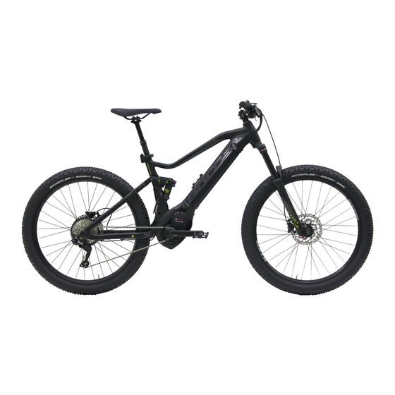
Description Description Overview 15 16 Figure 2: Bicycle viewed from the right, Six50 Evo 4 used as example Front wheel Fork Front mudguard Headlight Handlebars Stem Frame Seat post Saddle Pannier rack Reflector and rear light Rear mudguard Rear wheel Kickstand Chain Chain guard... -
Page 29: Wheel And Fork
Description Wheel and fork Figure 3: Components of the wheel – example showing front wheel Tire Suspension fork head with setting wheel Fork Spoke Quick release Valve Fork end of the suspension fork 3.2.1 Valve Each wheel has a valve. It is used to fill the tire with air. - Page 30 Description Dunlop valve The rider can easily exchange the valve and quickly release the air. The air pressure cannot be measured with this valve. Presta valve The presta valve requires a smaller hole in the rim, which is why it is especially suitable for the narrow rims of racing bicycles.
-
Page 31: Suspension
Description 3.2.2 Suspension Both forks and suspension forks are fitted in this model series. A suspension fork is based either on a steel spring or air suspension. Unlike a rigid fork, a suspension fork has two functions which improve floor contact and comfort: suspension and damping. -
Page 32: Suspension Fork Structure
Description Dampers which dampen compressive deflection movements, i.e. a compression load, are called compression dampers or compression dashpots. Dampers which dampen rebound deflection movements, i.e. a rebound load, are called rebound dampers or dashpots. 3.2.3 Suspension fork structure Figure 5: Example showing Suntour fork The stem and handlebars are fastened to the fork shaft (1). -
Page 33: Air Suspension Fork Structure
Description 3.2.3.1 Air suspension fork structure The fork of the bicycle features both air suspension and a compression damper, in addition to a rebound damper in some cases. Figure 6: Example showing Yari fork Diagram with the control panels: Air valve (1), valve cap (2) fork lock (3), quick release (4) and rebound damper adjuster (5) and the assembly groups: Air suspension fork (A), compression damper assembly group (B) and rebound damper assembly group (C) -
Page 34: Structure Of The Fox Rear Frame Damper
Description 3.2.3.2 Structure of the FOX rear frame damper The rear frame damper features air suspension, a compression damper and a rebound damper. 25-30% Figure 7: Example showing FOX rear frame damper Total damper deflection Rubber air chamber seal Negative distance O-ring... -
Page 35: Structure Of The Suntour Rear Frame Damper
Description 3.2.3.3 Structure of the Suntour rear frame damper The rear frame damper features air suspension, a compression damper and a rebound damper. Figure 8: Example showing Suntour rear frame damper Upper eye Total damper length Lower eye O-ring Sleeve Damper unit IFP (internal floating piston) Air valve... -
Page 36: Brake System
Description Brake system The bicycle is equipped with a disc brake. Figure 9: Rim brake components with details; Magura HS22 used as an example Rear wheel rim brake Brake booster Brake lining Handlebars with brake levers Front wheel rim brake The rim brake stops the wheel moving when the rider pulls the brake lever, causing two brake linings, positioned opposite one another, to be pressed onto... -
Page 37: Figure 10: Rim Brake Locking Lever, Closed (1) And Open (2)
Description The hydraulic rim brake features a locking lever Figure 10: Rim brake locking lever, closed (1) and open (2) The rim brake locking lever is not marked with any lettering. Only a specialist dealer may set the rim brake locking lever. -
Page 38: Electric Drive System
Description Electric drive system The bicycle is driven by muscle power via the chain drive. The force which is applied by pedalling in the direction of travel, drives the front chain wheel. The chain transmits the force onto the rear chain wheel and then onto the rear wheel. -
Page 39: Figure 12: Diagram Of Electric Drive System
Description The electric drive system is made up of 7 components: Figure 12: Diagram of electric drive system Headlight Display Control panel Down tube battery Rear light Motor • A charger which is designed for the battery. As soon as the required muscle power from the rider pedalling passes a certain level, the motor is activated gently and assists the pedalling motion of the rider. -
Page 40: Rechargeable Battery
Description 3.4.1 Rechargeable battery The lithium ion battery has an internal electronic protection circuit. It is matched to the charger and the bicycle. The battery temperature is monitored at all times. The battery is protected against deep discharge, overcharging, overheating and short circuit. -
Page 41: Operating And Charge Status Indicator
Description The bicycle has an integrated battery. Figure 13: Details of integrated battery Key to the battery lock Retainer guard Securing hook On-Off button (battery) Operating and charge status indicator Integrated battery housing 3.4.1.1 Operating and charge status indicator The five green LEDs on the operating and charge status indicator indicate the charge status when the battery is switched on. -
Page 42: Control Panel
Description 3.4.3 Control panel The control panel has six buttons. Figure 14: Overview of the control panel Symbol Surname Select button < Browse backwards button > Browse forwards button Plus button Push assist button – Minus button Table 8: Overview of the control panel 3.4.4 Display The display has two buttons to display the main drive... - Page 43 Description If the on-board computer is removed from its mount, power is supplied from the display battery. If the display battery is low, a warning message is shown on the screen. If the on-board computer is removed from its mount and not switched off, information on the last trip distance travelled and status information will be displayed after one another in a loop.
-
Page 44: Usb Port
Description Figure 15: Overview of the structure and operating elements of the display Symbol Driving light button Screen display On-Off button (display) USB port protective flap Table 10: Operating element overview 3.4.4.1 USB port There is a USB port underneath the rubber cover below the display. -
Page 45: Indicators
Description 3.4.4.2 Indicators Start screen The S T A R T S C R E E N will appear as soon as the display is inserted into the mount. The S T AR T S C R EE N has ten on-screen indicators: Figure 16: Overview of start screen Symbol... - Page 46 Description Status bar The indicators for the speed unit (1), battery charging (3), clock (4) and the driving light symbol (2) are featured in the status bar and are shown on every screen. Status screen You can use the browse backwards button on the S T A R T S C R E EN to access the S T A T U S S C R E E N .
- Page 47 Description You can make the following settings on the Quick Menu. Explanation R E S E T All journey data are reset to zero for the trip distance up until this point. [ D D . M M . Y Y ] E SH I F T Adjust items such as pedalling frequency or start gear.
- Page 48 Description briefly when the SPORT level of assistance is selected. Level of assistance When the drive system is switched on, the motor assistance is switched off. O F F The bicycle can be used like a normal bicycle by simply pedalling. The push assist system cannot be activated.
- Page 49 Description You can use the plus button (4) and the minus button (6) to select the required setting and use the select button to open it and other further sub-menus. You can use the <- button in the current setting menu to return to the previous menu.
-
Page 50: Technical Data
Technical data Technical data Bicycle 41°F–77 °F Transportation temperature 50°F–59 °F Ideal transportation temperature 41°F–77 °F Storage temperature 50°F–59 °F Ideal storage temperature 41°F–95 °F Operation temperature 59°F–77 °F Working environment temperature 50°F–86 °F Charging temperature Power output/system 250 W (0.25 kW) Shut-off speed - Class 1 bicycle 20 mph Shut-off speed - Class 3 bicycle... - Page 51 Technical data Display Internal lithium ion battery 3.7 V, 230 mAh 23°F–104 °F Operating temperature 14°F–122 °F Storage temperature 32 °F–104°F Charging temperature Protection rating IPx7 (with USB cover closed) Weight about 0.60 kg BLUETOOTH low energy® - Frequency 2400–2480 MHz - Transmitting capacity <...
- Page 52 Technical data Tightening torque Axle nut tightening torque 35 Nm - 40 Nm Handlebars clamping screw maximum 5 Nm - 7 Nm tightening torque* Table 19: Tightening torque values* *if there is no other data on the component...
-
Page 53: Transportation, Storage And Assembly
Transportation, storage and assembly Transportation, storage and assembly Transportation C r a s h c a u s e d b y u n i n t e n t i o n a l a c t i v a t i o n CAUTION There is a risk of injury if the drive system is activated unintentionally. - Page 54 Transportation, storage and assembly Bicycle rack systems which secure the bicycle NOTICE standing on its head by the handlebars or frame, generate inadmissible forces on the components during transportation. This can cause the supporting parts to break. Never use bicycle rack systems which secure the bicycle standing on its head by the handlebars or frame.
-
Page 55: Using The Transport Securing System
Transportation, storage and assembly 5.1.1 Using the transport securing system Insert the transport securing devices between the brake linings. The transport securing device is squeezed between the two linings. Figure 17: Fastening the transport securing device Storing R i s k o f f i r e a n d e x p l o s i o n d u e t o h i g h CAUTION t e m p e r a t u r e s Excessively high temperatures will damage batteries. -
Page 56: Break In Operation
Transportation, storage and assembly If the bicycle features a hydraulic seat post, fix only the lower seat post or the frame into a fitting stand to prevent damage to the upper seat post and the seat post lever. Never place a bicycle with a hydraulic seat post upside down on the floor;... -
Page 57: Preparing A Break In Operation
Transportation, storage and assembly 5.2.1.1 Preparing a break in operation Enable display storage mode. Remove the battery from the bicycle. Charge the battery to around 60% (three to four LEDs of the charge status indicator light up). ... -
Page 58: Assembly
Transportation, storage and assembly Assembly Crushing caused by unintentional activation CAUTION There is a risk of injury if the drive system is activated unintentionally. Remove the battery if it is not absolutely necessary for assembly. Assemble the bicycle in a clean and dry environment. ... -
Page 59: Unpacking
Transportation, storage and assembly 5.3.2 Unpacking Hand injuries caused by cardboard packaging CAUTION The shipping carton is closed with metal staples. There is a risk of puncture wounds and cuts when unpacking and crushing the packaging. Wear suitable hand protection. ... -
Page 60: Commissioning
Transportation, storage and assembly 5.3.4 Commissioning Fire and explosion caused by incorrect charger CAUTION Batteries which are recharged with an unsuitable charger may become damaged internally. This may result in fire or an explosion. Only ever use the battery with the supplied charger. ... - Page 61 Transportation, storage and assembly Initial commissioning check list Deactivate display storage mode. Check battery. The battery is partially charged when delivered. Fully charge the battery to ensure full power. Mount the wheels, quick release and pedals. ...
-
Page 62: Checking The Battery
Transportation, storage and assembly 5.3.4.1 Checking the battery Fire and explosion due to defective battery WARNING The safety electronics may fail if the battery is damaged or defective. The residual voltage can cause a short circuit. Batteries may self-ignite and explode. ... -
Page 63: Adjusting The Display Settings
Transportation, storage and assembly 5.3.4.3 Adjusting the display settings Settings must be made when the bicycle is stationary only. Insert the display in its mount. Press the browse backwards button. The status screen is open. Press the select button. The SE T TI N G S page will open. -
Page 64: Mounting The Wheel In The Suntour Fork
Transportation, storage and assembly 5.3.5 Mounting the wheel in the Suntour fork Alternative 5.3.5.1 Mounting the wheel with screw-on axle (15 mm) Alternative Insert the axle completely on the drive side. Figure 18: Fully inserting the axle Tighten the axle with a 5 mm hexagon socket spanner to 8–10 Nm. -
Page 65: Figure 20: Pushing The Quick Release Lever Into The Axle
Transportation, storage and assembly Insert the securing screw on the non-drive side. Figure 20: Pushing the quick release lever into the axle Tighten the securing screw with a 5 mm hexagon socket spanner to 5–6 Nm. The lever is mounted. Figure 21: Tightening the securing screw... -
Page 66: Mounting The Wheel With Screw-On Axle (20 Mm)
Transportation, storage and assembly 5.3.5.2 Mounting the wheel with screw-on axle (20 mm) Alternative Insert the axle completely on the drive side. Figure 22: Tightening the inserted axle Tighten the securing clip with a 4 mm hexagon socket spanner to 7 Nm. Figure 23: Tightening the axle... -
Page 67: Mounting The Wheel With A Quick Release Axle
Transportation, storage and assembly 5.3.5.3 Mounting the wheel with a quick release axle Alternative Crash caused by loose quick release axle CAUTION A faulty or incorrectly installed quick release axle may become caught in the brake disc and block the wheel. This will cause a crash. -
Page 68: Figure 24: Pushing The Axle Into The Hub
Transportation, storage and assembly Insert the axle into the hub on the drive side. Clamping version II. Figure 24: Pushing the axle into the hub Tighten the axle with the red handle. Figure 25: Tightening the axle... -
Page 69: Figure 26: Pushing The Quick Release Lever Into The Axle
Transportation, storage and assembly Push the quick release lever into the axle. Figure 26: Pushing the quick release lever into the axle Reverse the quick release lever. The lever is secured. Figure 27: Securing the lever... -
Page 70: Figure 28: Perfect Position For The Clamping Lever
Transportation, storage and assembly Check the position and clamping force of the quick release lever. The quick release lever must be flush with the lower housing. You must be able to see a slight impression on the palm of your hand when you close the quick release lever. -
Page 71: Mounting The Wheel With A Quick Release
Transportation, storage and assembly 5.3.6 Mounting the wheel with a quick release Alternative Crash caused by unfastened quick release CAUTION A faulty or incorrectly installed quick release may become caught in the brake disc and block the wheel. This will cause a crash. ... -
Page 72: Figure 30: Open And Closed Flange
Transportation, storage and assembly Before mounting, ensure that the quick release flange is extended. Open the lever completely. Figure 30: Open and closed flange Push in the quick release until you hear a clicking sound. Make sure that the flange is extended. Figure 31: Pushing the quick release in... -
Page 73: Figure 32: Adjusting The Clamping
Transportation, storage and assembly Adjust the clamping with a half-open clamping lever until the flange reaches the fork end. Figure 32: Adjusting the clamping Fully close the quick release. Check the quick release to ensure it is firmly in place and adjust on the flange if necessary. -
Page 74: Mounting The Wheel In The Fox Fork
Transportation, storage and assembly 5.3.7 Mounting the wheel in the FOX fork Alternative 5.3.7.1 Mounting the wheel with the quick release (15 mm) Alternative The procedure for installing the 15 x 100 mm and 15 x 110 mm quick releases is the same. ... -
Page 75: Adjusting The Fox Quick Release
Transportation, storage and assembly The lever must be 1 to 20 mm ahead of the fork leg in the closed position. 1-20 mm Figure 35: Spacing between lever and fork leg If the lever is tensioned too little or too much when closed in the recommended position (1 to 20 mm ahead of the fork), the quick release must be adjusted. - Page 76 Transportation, storage and assembly Record the axle setting value (4) indicated by the directional arrow (3). Loosen the axle nut securing screw (2) with a 2.5 mm hex key by approx. four revolutions, but do not remove the screw completely. ...
-
Page 77: Mounting The Wheel With Kabolt Axles
Transportation, storage and assembly 5.3.7.3 Mounting the wheel with Kabolt axles Alternative The procedure for installing the 15 x 100 mm and 15 x 110 mm Kabolt axles is the same. Place the front wheel in the fork ends of the fork. Push the Kabolt axle through the fork end on the non-drive side and hub. -
Page 78: Checking The Stem And Handlebars
Transportation, storage and assembly 5.3.7.4 Checking the stem and handlebars Checking connections Stand in front of the bicycle to check whether the handlebars, stem and fork shaft are firmly attached to one another. Clamp the front wheel between your legs. Grasp the handlebar grips. Try to twist the handlebars towards the front wheel. -
Page 79: Sale Of The Bicycle
Transportation, storage and assembly Checking the headset backlash To check the handlebar headset backlash, close the quick release lever on the stem. Place the fingers of one hand on the upper headset cup, pull the front wheel brake with the other hand and try to push the bicycle backwards and forwards. -
Page 80: Before The First Ride
Before the first ride Before the first ride Crash caused by incorrectly adjusted torques CAUTION If a screw is fastened too tightly, it may break. If a screw is not fastened enough, it may loosen. This will result in a crash and injuries. ... -
Page 81: Determining The Seat Height
Before the first ride Place the saddle tilt in the horizontal position to adjust the bicycle to your needs for the first time. Figure 38: Horizontal saddle tilt 6.1.2 Determining the seat height To determine the seat height safely, either push the bicycle near to a wall, so that you can lean on the wall to support yourself or ask another person to hold the bicycle for you. -
Page 82: Adjusting The Seat Height With Quick Release
Before the first ride Figure 39: Optimal saddle height 6.1.3 Adjusting the seat height with quick release Open the quick release on the seat post to change the seat height. To do so, pull the clamping lever away from the seat post. Figure 40: Seat post quick release (3) with clamping lever (5) and setting bolt (4) in the open position (1) and in the direction of the closed... -
Page 83: Setting The Height-Adjustable Seat Post
Before the first ride Set the seat post at the required height. Crash caused by an excessively high seat post CAUTION setting A seat post with is set too high will cause the seat post or the frame to break. This will result in a crash and injuries. -
Page 84: Lowering The Saddle
Before the first ride Figure 42: The seat post activation lever can be mounted either on the left (1) or the right (2) side of the handlebars 6.1.4.1 Lowering the saddle To lower the saddle, press your hand down on the saddle or sit on the saddle. -
Page 85: Adjusting The Seat Position
Before the first ride 6.1.5 Adjusting the seat position The saddle can be shifted on the saddle frame. The right horizontal position ensures an optimal leverage position for legs. This prevents knee pain and painful incorrect pelvis positions. If you have displaced the saddle more than 10 mm, you then need to adjust the saddle height again since both settings affect one another. -
Page 86: Adjusting The Handlebars
Before the first ride Adjusting the handlebars The handlebars must only be adjusted while the bicycle is stationary. Unfasten and adjust the designated screw connections, and clamp them with the maximum tightening torque for the clamping screws of the handlebars. -
Page 87: Adjusting The Height Of The Handlebars
Before the first ride 6.2.1 Adjusting the height of the handlebars Crash caused by incorrectly set clamping force CAUTION Excessively high clamping force will damage the quick release and cause it to lose its function. Insufficient clamping force will cause a detrimental transmission of force. -
Page 88: Turning The Handlebars To The Side
Before the first ride 6.2.2 urning the handlebars to the side Alternative Crash caused by incorrectly set clamping force CAUTION Excessively high clamping force will damage the quick release and cause it to lose its function. Insufficient clamping force will cause a detrimental transmission of force. -
Page 89: Checking The Clamping Force Of The Quick Releases
Before the first ride 6.2.2.1 Checking the clamping force of the quick releases Open and close the quick releases on the stem or the seat post. The clamping force is sufficient if the clamping lever can be moved easily from the open final position into the middle and has to be pressed with the fingers or base of the thumb from the middle point onwards. -
Page 90: Adjusting The Grip Distance
Before the first ride The brake lever moves closer to the handlebar grip. Re-adjust the grip distance as necessary. The lever pressure point activates sooner. Figure 46: Using the twist knob (1) to adjust the pressure point 6.3.2 Adjusting the grip distance Crash caused by incorrectly set grip distance WARNING... -
Page 91: Adjusting The Grip Distance On A Magura Brake Lever
Before the first ride Figure 47: Brake lever grip distance 6.3.2.1 Adjusting the grip distance on a Magura brake lever Alternative Use a T25 TORX® wrench to turn the setting screw to adjust the grip distance. Turn the setting screw in the minus (-) direction. ... -
Page 92: Adjusting The Suspension Of The Suntour Fork
Before the first ride Adjusting the suspension of the Suntour fork Alternative The following Suntour forks can be installed in this series of models: Aion-35 Boost Air suspension fork Air suspension fork Steel suspension fork XCM-ATB Steel suspension fork Steel suspension fork XCR32 Air suspension fork XCR34... -
Page 93: Adjusting The Negative Deflection
Before the first ride It is advisable to make a note of the basic setting. This way, it can be used as the starting point for subsequent, optimised settings and to safeguard against unintentional changes. 6.4.1 Adjusting the negative deflection Negative deflection (SAG) is compression of the fork caused by the weight of the rider and their gear (e.g. - Page 94 Before the first ride Remove the high-pressure pump. Rider weight AION, NEX XCR 32, XCR 34 < 55 kg 35 - 50 psi 40 - 55 psi 55 - 65 kg 50 - 60 psi 55 - 65 psi 65 - 75 g 60 - 70 psi 65 - 75 psi...
-
Page 95: Adjusting The Steel Suspension Fork Negative Deflection
Before the first ride Once the "SAG" is correct, re-tighten the blue air cover cap clockwise. If you cannot achieve the desired "SAG", you may need to make an internal adjustment. For this purpose, contact your specialist dealer. 6.4.1.2 Adjusting the steel suspension fork negative deflection Alternative... -
Page 96: Adjusting The Rebound
Before the first ride The ideal setting in relation to the weight of the rider has been achieved when the shock absorber deflects 3 mm under the stationary load of the rider. Reattach the cover after the adjustment. 6.4.2 Adjusting the rebound Alternative The rebound defines the speed at which the fork... -
Page 97: Adjusting The Suspension Of The Fox Fork
Before the first ride Adjusting the suspension of the FOX fork Alternative Crash caused by incorrectly set suspension CAUTION If the suspension is adjusted incorrectly, the fork may become damaged, so that problems may occur when steering. This will result in a crash and injuries. ... - Page 98 Before the first ride When adjusting the "SAG", ensure that each compression adjuster is in the open position, i.e. turned clockwise until it stops. The pressure is to be measured at an ambient temperature of 70 to 75 °F. ...
- Page 99 Before the first ride Measure the distance between the crown and the dust wiper of the fork. This distance is the "total deflection of the fork." Push the O-ring downward against the dust wiper of the fork. If an O-ring is not available, attach a cable tie to the stanchion temporarily.
-
Page 100: Adjusting The Rebound
Before the first ride 6.5.2 Adjusting the rebound The rebound defines the speed at which the fork rebounds after being loaded. The rebound setting depends on the air pressure setting. Higher "SAG" settings require lower rebound settings. Turn the rebound adjuster clockwise to the closed position until it stops. -
Page 101: Adjusting The Suntour Rear Frame Damper
Before the first ride Adjusting the Suntour rear frame damper Alternative 6.6.1 Adjusting the negative deflection If the air pressure in the rear frame damper is NOTICE exceeded or undershot, the damper can be permanently damaged. Do not exceed the maximum air pressure of 300 psi (20 bar). -
Page 102: Adjusting The Rebound
Before the first ride Push the O-ring downward against the rubber air chamber seal. Get off the bicycle without allowing it to deflect. Measure the distance between the rubber air chamber seal and the O-ring. This dimension is the "SAG."... -
Page 103: Setting The Compression
Before the first ride 6.6.3 Setting the compression The compression damper setting of the rear frame damper makes it possible to set the damper according to the conditions of the ground. The compression damper setting specifies the speed at which the rear frame damper deflects after being loaded. -
Page 104: Adjusting The Fox Rear Frame Damper
Before the first ride Adjusting the FOX rear frame damper Alternative 6.7.1 Adjusting the negative deflection If the air pressure in the rear frame damper is NOTICE exceeded or undershot, the damper can be permanently damaged. Do not exceed the maximum air pressure of 350 psi (24.1 bar). - Page 105 Before the first ride 25-30% Figure 55: FOX rear frame damper: The negative deflection (2) is the distance between the O-ring (4) and the rubber air chamber seal (1). The total deflection of the rear frame damper (5) is the distance between the end of the rear frame damper (3) and the rubber air chamber seal (1) ...
-
Page 106: Adjusting The Rebound
Before the first ride 6.7.2 Adjusting the rebound The rebound defines the speed at which the rear frame damper rebounds after being loaded. The rebound setting depends on the air pressure setting. Higher "SAG" settings require lower rebound settings. Figure 56: FOX rebound adjuster (1) on the rear frame damper ... -
Page 107: Retracting Brake Linings
Before the first ride Air pressure (psi) Recommended rebound setting < 100 Open (anti-clockwise) 100 - 120 120 - 140 140 - 160 160 - 180 180 - 200 200 - 220 220 - 240 240 - 260 260 - 280 280 - 300 Table 27: Filling pressure table of the FOX air fork... -
Page 108: Operation
Operation Operation Crash caused by loose clothing CAUTION Laces, scarves and other loose items may become entangled in the spokes on the wheels and the chain drive. This may cause you to fall from the bicycle and injure yourself. Wear sturdy footwear and close-fitting clothing. Crash caused by soiling CAUTION Heavy soiling can impair the functions of the bicycle,... - Page 109 Operation You can be ride the bicycle within a temperature range between 41 °F and 95 °F. The effectiveness of the drive system is restricted outside of this temperature range. 41°F–95 °F Operation temperature Moisture penetrating at low temperatures may impair individual bicycle functions due to the open structural design.
-
Page 110: Before Each Ride
Operation Before each ride Crash caused by difficult-to-spot damage CAUTION If the bicycle topples over or you have a fall or an accident, there may be difficult-to-spot damage to components such as the brake system, quick releases or frame. This may cause you to fall from the bicycle and injure yourself. -
Page 111: Check List Before Each Ride
Operation Check list before each ride Check the bicycle before each ride. Do not use the bicycle if there are any anomalies. Check that the bicycle is complete. Check that the lighting, reflector and brake, for instance, are ... -
Page 112: Using The Kickstand
Operation Using the kickstand Crash caused by a lowered kickstand CAUTION The kickstand does not fold up automatically. There is a risk of crashing if riding with the kickstand lowered. Raise the kickstand completely before the ride. The heavy weight of the bicycle may cause the NOTICE kickstand to sink into soft ground and the bicycle may topple and crash over. -
Page 113: Using The Pannier Rack
Operation Using the pannier rack Crash caused by loaded pannier rack CAUTION The riding performance of the bicycle changes with a loaded pannier rack, in particular when steering and braking. This can lead to a loss of control. This may cause you to fall from the bicycle and injure yourself. - Page 114 Operation The maximum load bearing capacity is indicated on the NOTICE pannier rack. Never exceed the permitted total weight when packing the bicycle. Never exceed the maximum load bearing capacity of the pannier rack. Never modify the pannier rack. ...
-
Page 115: Rechargeable Battery
Operation Rechargeable battery Fire and explosion due to defective battery WARNING The safety electronics on damaged or faulty batteries may fail. The residual voltage can cause a short circuit. The batteries may self-ignite and explode. Remove batteries with external damage from service immediately and never charge them. - Page 116 Operation Fire and explosion caused by short circuit CAUTION Small metal objects may jumper the electrical connections of the battery. The batteries may self- ignite and explode. Keep paper clips, screws, coins, keys and other small parts away from the battery and do not insert them into the battery.
-
Page 117: Down Tube/Seat Tube Battery
Operation Fire and explosion caused by penetration by water CAUTION The battery is only protected from simple spray water. Penetration by water can cause a short circuit. The battery may self-ignite and explode. Never immerse the battery in water. ... -
Page 118: Inserting The Down Tube/Seat Tube Battery
Operation 7.5.1.2 Inserting the down tube/seat tube battery Figure 57: Removing and inserting the down tube battery (3) Place the down tube battery on the contacts in the lower mount. (4) Remove the key from the lock. Tip the battery into the top mount as far as it will go. ... -
Page 119: Integrated Battery
Operation 7.5.2 Integrated battery Alternative Before the battery is to be removed or inserted, switch off the battery and the drive system. 7.5.2.1 Removing the integrated battery Figure 58: Removing the integrated battery (1) Open the battery lock with the key. ... -
Page 120: Inserting The Integrated Battery
Operation 7.5.2.2 Inserting the integrated battery Figure 59: Inserting the integrated battery (1) Place the battery with the contacts first into the lower mount. (2) Tilt the integrated battery up, so that it is held by the retainer guard. ... -
Page 121: Charging The Battery
Operation 7.5.3 Charging the battery Risk of fire and explosion due to faulty battery WARNING The safety electronics on damaged or faulty batteries may fail. The residual voltage can cause a short circuit. The batteries may self-ignite and explode. Never charge a defective battery. Fire caused by overheated charger CAUTION The charger heats up when charging the battery. - Page 122 Operation The ambient temperature during the charging process must be within the range from 32 °F to 104 °F. The battery can remain on the bicycle or be removed for charging. Interrupting the charging process does not damage the battery.
-
Page 123: Charging The Dual Battery
Operation 7.5.4 Charging the dual battery Alternative Risk of fire and explosion due to faulty battery WARNING The safety electronics on damaged or faulty batteries may fail. The residual voltage can cause a short circuit. The batteries may self-ignite and explode. ... -
Page 124: Charging Process When Two Batteries Are Used
Operation One of the charging sockets is not accessible or is closed with an end cap on bicycles with two batteries. Charge the batteries using the accessible charging socket only. Never open a closed charging socket. Charging via a pre-closed charging socket can cause irreparable damage. -
Page 125: Waking The Battery
Operation 7.5.5 Waking the battery When not used for a longer period, the battery switches to sleep mode to self-protect. The LEDs of the operating and charge status indicator do not light Press the On-Off button (battery). The battery's operating and charge status indicator indicates the charge status. -
Page 126: Electric Drive System
Operation Electric drive system 7.6.1 Switching on the drive system Crash caused by lack of readiness for braking CAUTION When it is switched on, the drive system can be activated by the application of force on the pedals. There is a risk of a crash if the drive is activated unintentionally, and the brake is not reached. -
Page 127: Switching Off The Drive System
Operation If the drive system is switched on, the drive is activated as soon as the pedals are moved with sufficient force (except if in push assist mode or the level of assistance is "OFF"). The motor power is determined by the level of assistance set on the display. -
Page 128: Display
Operation Display Crash caused by to distraction CAUTION A lack of concentration while riding increases the risk of an accident. This may cause a crash with serious injuries as a consequence. Never allow yourself to be distracted by the display. ... -
Page 129: Charging The Display Battery
Operation 7.7.1 Charging the display battery You can recharge the display battery either on the bicycle or via the USB port. 7.7.1.1 Charging the display battery on bicycle The display will only charge when switched on. NOTICE Switch the display on. ... -
Page 130: Storage Mode
Operation 7.7.2 Storage mode The display features a power-saving storage mode, which minimises discharge from the display battery. The date and time are eliminated during storage mode. 7.7.2.1 Activating the storage mode The display will no longer start up when you press the on-off button (display) once when in storage mode. -
Page 131: Removing The Display
Operation 7.7.3.1 Removing the display Take hold of the display at its top end. Pull the display forwards away from the contacts to the drive unit until it is released from its magnetic mount. The system is switched off by removing the display Figure 60: Pull the display (2) out of its mount (1) away from the contacts with the display blocking screw (3) -
Page 132: Securing The Display
Operation 7.7.3.3 Securing the display The blocking screw does not offer protection against NOTICE theft. Position the display in its mount. Fasten the blocking screw (M3, 6 mm in length) into the designated thread in the display from below. You may damage the display if you use a longer screw. -
Page 133: Switching On The Display
Operation The display and sufficiently charged battery must be in place on the bicycle to use the USB port. Open protective flap on the USB port on the display. Connect the external device USB port with the USB port on the on-board computer using a micro A–micro B USB charging cable. -
Page 134: Using The Push Assist System
Operation 7.7.7 Using the push assist system Injury from pedals or wheels CAUTION The pedals and the drive wheel turn when the push assist system is used. There is a risk of injury if the bicycle wheels are not in contact with the ground when the push assist system is used (e.g. -
Page 135: Using The Driving Light
Operation 7.7.8 Using the driving light The drive system needs to be already switched on to turn on the driving light. Press the driving light button on the display. The front light and rear light are both switched on (driving light symbol is displayed) or switched off (driving light symbol is not displayed) at the same time. - Page 136 Operation The display is operated using five buttons on the control panel. Figure 61: Overview of the control panel Symbol Designation Select button < Browse backwards button > Browse forwards button Plus button Push assist button – Minus button Table 28: Overview of the control panel You can use the browse backwards button (2) and the browse forwards button (3) to access the...
-
Page 137: Opening The Start Screen
Operation You can use the select button (1) to perform the following functions: - Gain access to the Q U I C K M EN U while riding. - Open the S E T T I N G S M E N U in the S T A T US S C R E EN while the bicycle is stationary. -
Page 138: Opening The Quick Menu
Operation 7.7.15 Opening the Quick Menu You can use the Q U I C K M E N U to display selected settings which can also be adjusted while you are riding. You cannot access them from the S TA TU S S C R E E N . -
Page 139: Gear Shift
Operation Gear shift The selection of the appropriate gear is a prerequisite for a physically comfortable ride and making sure that the electric drive system functions properly. The ideal pedalling frequency is between 70 and 80 revolutions per minute. It is advisable to stop pedalling briefly when changing gears. -
Page 140: Brake
Operation Brake Hydraulic fluid can be fatal if it is swallowed and DANGER penetrates into the respiratory system Hydraulic fluid may leak out after an accident or due to material fatigue. Hydraulic fluid can be fatal if swallowed and inhaled. First aid treatment ... - Page 141 Operation After contact with eyes Rinse eyes under flowing water for at least ten minutes with the lids open; also rinse under lids. Consult eye doctor if pain or discomfort continues. After ingestion Rinse out mouth with water Never induce vomiting! Risk of aspiration! ...
- Page 142 Operation Crash caused by brake failure WARNING Oil or lubricant on the brake disc in a disc brake or on the rim of a rim brake can cause the brake to fail completely. This may cause a crash with serious injuries as a consequence.
- Page 143 Operation Crash caused by incorrect use CAUTION Handling the brake improperly can lead to loss of control or crashes, which may result in injuries. Shift your body weight back and down as far as possible. Practise braking and emergency braking before the bicycle is used in public spaces.
-
Page 144: Using The Brake Lever
Operation 7.9.1 Using the brake lever Figure 63: Front (2) and rear (1) brake lever; Shimano brake used as an example Pull the left brake lever for the front wheel brake and the right lever for the rear wheel brake until the desired speed is reached. -
Page 145: Suspension And Damping
Operation 7.10 Suspension and damping 7.10.1 Adjusting the compression of the Suntour fork Alternative The compression adjuster makes it possible to make quick adjustments to the suspension behaviour of the fork to suit changes in terrain. It is intended for adjustments made during the ride. -
Page 146: Adjusting The Compression Of The Fox Fork
Operation 7.10.2 Adjusting the compression of the Fox fork Alternative The compression adjuster makes it possible to make quick adjustments to the suspension behaviour of the fork to suit changes in terrain. It is intended for adjustments made during the ride. Figure 65: FOX compression adjuster with the OPEN (1) and HARD (2) positions... -
Page 147: Adjusting The Compression Of The Suntour Damper
Operation 7.10.3 Adjusting the compression of the Suntour damper Alternative The compression adjuster makes it possible to make quick adjustments to the suspension behaviour of the damper to suit changes in terrain. It should never be used while riding on rough terrain. Figure 66: Suntour compression adjuster open (1) ... -
Page 148: Adjusting The Compression Of The Fox Damper
Operation 7.10.4 Adjusting the compression of the Fox damper Alternative The compression adjuster makes it possible to make quick adjustments to the suspension behaviour of the damper to suit changes in terrain. It is intended for adjustments made during the ride. Figure 68: FOX compression adjuster on the rear frame damper with the OPEN (1), MEDIUM (2) and HARD (3) positions... - Page 149 Operation The FOX rear frame damper features fine adjustment for the OPEN position. We recommend that fine adjustments be made when the compression adjuster is in the MEDIUM or HARD position. Pull out the adjuster. Turn the adjuster to position 1, 2 or 3. Setting 1 is for the softest riding performance, whereas 3 is for the hardest.
-
Page 150: Maintenance
Maintenance Maintenance Cleaning check list Clean pedals after each ride Clean suspension fork and, if necessary, rear after each ride frame damper Clean the battery once a month every Chain (mainly tarmacked road) 250–300 km Basic cleaning and preservation of all at least every six ... - Page 151 Maintenance Service check list Functional check on the suspension fork every 50 hours Suspension fork maintenance and every 100 hours or at dismantling least once a year Complete maintenance of the rear frame every 125 hours damper ...
-
Page 152: Cleaning And Servicing
Maintenance Cleaning and servicing Crash and falling caused by unintentional activation CAUTION There is a risk of injury if the drive system is activated unintentionally. Remove the battery before cleaning. The following servicing measures must be performed regularly. Servicing can be performed by the operator and rider. -
Page 153: Basic Cleaning
Maintenance 8.1.2 Basic cleaning Crash caused by brake failure CAUTION The braking effect may be unusually poor temporarily after cleaning, servicing or repairing the bicycle. This may cause you to fall from the bicycle and injure yourself. Never apply care products or oil to the brake discs or brake linings, or the braking surfaces on the rims. -
Page 154: Cleaning The Frame
Maintenance 8.1.2.1 Cleaning the frame Soak dirt stains on the frame with dish-washing detergent if the dirt is thick and ingrained. After leaving it to soak for a time, remove the dirt and mud with a sponge, brush and toothbrush. ... -
Page 155: Cleaning The Drive Elements
Maintenance 8.1.2.5 Cleaning the drive elements Spray the cassette, the chain wheels and the front derailleur with a degreasing agent. Clean coarse dirt with a brush after soaking for a short time. Wash down all parts with dish-washing detergent and a toothbrush. -
Page 156: Cleaning The Battery
Maintenance 8.1.2.7 Cleaning the battery Fire and explosion caused by penetration by water CAUTION The battery is only protected from simple spray water. Penetration by water can cause a short circuit. The battery may self-ignite and explode. Never clean the battery with a high-pressure water device, water jet or compressed air. -
Page 157: Cleaning The Display
Maintenance 8.1.2.9 Cleaning the display If water enters into the display, it will be permanently NOTICE damaged. Never immerse the display in water. Never clean with a high-pressure water device, water jet or compressed air. Never use cleaning agents. ... -
Page 158: Servicing
Maintenance 8.1.3 Servicing 8.1.3.1 Servicing the frame Dry frame after cleaning Spray with care oil Clean off the care oil again after a short time. 8.1.3.2 Servicing the stem Apply silicone or Teflon oil to the stem shaft tube and the quick release lever pivot point. - Page 159 Maintenance 8.1.3.6 Servicing the chain Grease the chain thoroughly with chain oil after cleaning. 8.1.3.7 Servicing the drive elements Service front and rear derailleur articulated shafts and jockey wheels with Teflon spray.
- Page 160 Maintenance Maintenance Crash and falling caused by unintentional activation CAUTION There is a risk of injury if the drive system is activated unintentionally. Remove the battery before maintenance. The following maintenance measures must be carried out regularly [ Check list, page 148]. They can be ...
- Page 161 Maintenance • The rims with visible wear indicator are worn as soon as the black, all-round groove on the pad friction surface is no longer visible. We recommend that you also replace the rims with every second brake lining replacement. ...
- Page 162 Maintenance 8.2.5 Stem The stem and quick release system should be inspected at regular intervals. The specialist dealer should adjust them if necessary. If the hexagon socket head screw is also loosened, the headset backlash also needs to be adjusted. Medium-strength thread locker, such as Loctite blue, then needs to be applied to the loosened screws and the screws tightened as per the...
- Page 163 Maintenance 2 cm Figure 70: Checking the chain and belt tension If a hub gear is featured, the rear wheel must be pushed backwards or forwards to tighten the chain. This should be done by a specialist only. 8.2.7 USB port Any moisture which enters through the USB port may NOTICE...
- Page 164 Maintenance Service Crash and falling caused by unintentional activation CAUTION There is a risk of injury if the drive system is activated unintentionally. Remove the battery before the service. Crash caused by material fatigue CAUTION If the service life of a component has expired, the component may suddenly fail.
- Page 165 Maintenance The specialist dealer will fully inspect the interior and exterior of the rear frame damper, overhaul the rear frame damper, replace all air seals of air forks, overhaul the air suspension, change the oil and replace the dust wipers. ...
- Page 166 Maintenance Adjusting and repairing Crash and falling caused by unintentional CAUTION activation There is a risk of injury if the drive system is activated unintentionally. Remove the battery before the service. 8.4.1 Use original parts and lubricants only The individual parts of the bicycle have been selected carefully and to matched to each other.
- Page 167 Maintenance 8.4.2 Wheel quick release Crash caused by unfastened quick release CAUTION A faulty or incorrectly installed quick release may become caught in the brake disc and block the wheel. This will cause a crash. Install the front wheel quick release lever on the opposite side to the brake disc.
- Page 168 Maintenance 8.4.2.1 Clamping the clamping lever The clamping lever for the quick release is marked OPEN and CLOSE. If you can read the word OPEN, the quick release is open. If you can read the word CLOSE, the quick release is clamped. ...
- Page 169 Maintenance Checking and setting the clamping force of the quick releases If the clamping lever cannot be moved into the final position just by pushing it with the hand, or if it is too loose, its clamping force will need to be readjusted. ...
- Page 170 Maintenance 8.4.2.4 Clamping version III If the clamping force is insufficient, have the specialist NOTICE dealer inspect it. Figure 73: Quick release, version III, with axle (1) and clamping lever (2) Push the axle into the hub as far as it will go with the clamping lever completely open.
- Page 171 Maintenance 8.4.2.5 Clamping version IV Push the axle into the hub as far as it will go with the clamping lever open. Screw the clamping lever clockwise into the correct final position. Clamp the clamping lever. Setting the clamping force If the clamping force is set too high, the clamping lever cannot be pushed into the closed final position.
- Page 172 Maintenance 8.4.2.6 Clamping version V Crash caused by unfastened quick release CAUTION The clamping force of the quick release lever is set once during assembly and is not an indication that the wheel axle is sufficiently fastened. The axle may come loose if the closed quick release is turned.
- Page 173 Maintenance Turn the axle on the quick release clockwise until the axle is firmly in place. Pull the lever from the recess and clamp it properly. The clamping force of the lever is not an indication of the tightening torque of the axle. Setting the clamping force If the clamping lever cannot be moved into its proper final position by pushing it with the hand, or if it is too...
- Page 174 Maintenance Open the quick release lever. Connect a 2.5 mm hexagon socket spanner to the middle of the clamping lever. Turn the hexagon socket spanner: • turn clockwise to increase the clamping force and • anti-clockwise to reduce the clamping force. ...
- Page 175 Maintenance Adjusting the tire pressure 8.4.3 8.4.3.1 Dunlop valve The tire pressure cannot be measured on the simple Dunlop valve. The tire pressure is therefore measured in the filling hose when pumping slowly with the bicycle pump. It is recommendable to use a bicycle pump with a pressure gauge.
- Page 176 Maintenance 8.4.3.2 Presta valve It is recommendable to use a bicycle pump with a pressure gauge. The operating instructions for the bicycle pump must be adhered to. Unscrew and remove the valve cap. Open the knurled nut around four turns. ...
- Page 177 Maintenance 8.4.3.3 Schrader valve It is recommendable to use a bicycle pump with a pressure gauge. The operating instructions for the bicycle pump must be adhered to. Unscrew and remove the valve cap. Connect the bicycle pump. ...
- Page 178 Maintenance 8.4.4 Adjusting the gear shift If you cannot select the gears effortlessly, you will need to adjust the setting for the shift cable tension. Carefully pull the adjusting sleeve away from the shifter housing, turning it as you do so. ...
- Page 179 Maintenance 8.4.4.2 Cable-operated gear shift, dual-cable Alternative For a smooth gear shift, set the adjusting sleeves underneath the chain stay on the frame. The shift cable has around 1 mm play when it is pulled out gently. Figure 82: Adjusting sleeves (2) on two alternative versions (A and B) of a dual-cable cable-operated gear shift on the chain stay (1)
- Page 180 Maintenance 8.4.4.3 Cable-operated twist grip, dual-cable Alternative For a smooth gear shift, set the adjusting sleeves on the shifter housing. There is noticeable play of around 2–5 mm (1/2 gear) when twisting the twist grip. Figure 83: Twist grip with adjusting sleeves (1) and play of the gear shift (2)
- Page 181 Maintenance 8.4.5 Offsetting the brake lining wear 8.4.5.1 Hydraulically operated rim brake Alternative The setting bolt on the brake lever of the hydraulic rim brake is used to offset the brake lining wear. If the profile of the brake linings has a remaining depth of just 1 mm, the brake linings need to be replaced.
- Page 182 Maintenance 8.4.6 Replacing the lighting Alternatively a 3 watt or 1.5 watt lighting system can be installed. Only use components of the respective power class for replacement. 8.4.7 Setting the headlight The headlight must be set, so that its light beam meets the road 10 m in front of the bicycle.
- Page 183 Maintenance 8.4.9 Replacing the lighting Alternatively a 3 watt or 1.5 watt lighting system can be installed. Only use components of the respective power class for replacement. 8.4.10 Setting the headlight The headlight must be set, so that its light beam meets the road 10 m in front of the bicycle.
- Page 184 Maintenance 8.4.12 First aid Fire and explosion due to faulty batteries WARNING The safety electronics on damaged or faulty batteries may fail. The residual voltage can cause a short circuit. The batteries may self-ignite and explode. Batteries with external damage must be removed from service immediately.
- Page 185 Maintenance 8.4.13 The electric drive system or display do not start If the display and/or the drive system do not start up, proceed as follows: Check whether the battery is switched on. If not, start the battery. Contact specialist dealer if the charge status indicator LEDs do not light up.
- Page 186 Maintenance 8.4.13.1 System messages If an error message is displayed, run through the following actions: Make a note of the system message. Shut off and re-start the drive system. If the system message is still displayed, remove and then re-insert the battery.
- Page 187 Maintenance Code Remedy 540, 605 The bicycle is outside the permitted temperature range. Switch the bicycle off to cool the drive unit down or warm it up to the permitted temperature range. Re-start the system. Contact your specialist dealer if the problem persists.
- Page 188 Maintenance Accessories For bicycles without a kickstand we recommend a parking stand into which either the front or rear wheel can be inserted securely. The following accessories are recommended: Description Article number Protective cover for electrical 080-41000 ff components Panniers, system component* 080-40946 Rear wheel basket, system 051-20603...
- Page 189 Maintenance Crash caused by improper handling CAUTION When using child seats, the riding properties and the stability of the bicycle change considerably. This can cause a loss of control, a crash and injuries. You should practice how to use the child seat safely and reliably before using the bicycle in public spaces.
- Page 190 Maintenance The specialist dealer will advise on choosing a suitable child seat system for the child and the bicycle. The specialist dealer must mount the child seat the first time to ensure that it is safely fitted. When installing a child seat, the specialist dealer makes sure that the seat and the fastening mechanism for the seat are suitable for the bicycle and that all components are installed and firmly fastened.
- Page 191 Maintenance Figure 85: Trailer sign The specialist dealer will advise on choosing a suitable trailer system for the bicycle. The specialist dealer must install the trailer the first time to ensure that it is safely fitted. 8.5.3 Pannier rack The specialist dealer will advise on choosing a suitable pannier rack.
- Page 192 Recycling and disposal Recycling and disposal Risk of fire and explosion WARNING The safety electronics on damaged or faulty batteries may fail. The residual voltage can cause a short circuit. The batteries may self-ignite and explode. Remove batteries with external damage from service immediately and never charge them.
- Page 193 Recycling and disposal This device is marked according to the European Directive 2012/19/EU on waste electrical and electronic equipment – WEEE. The directive provides the framework for the return and recycling of used devices across the EU. The bicycle, battery, display and charger are recyclable materials.
- Page 194 Appendix Appendix 10.1 System messages Code Cause Remedy One or more display buttons are blocked Check whether buttons are jammed because dirt has got into them, for example. Clean the buttons if necessary. Connection problem with the Have ports and connections checked. control panel ...
- Page 195 Appendix Code Cause Remedy Error in USB port Re-start the system. Contact your specialist dealer if the problem persists. Internal display error Have display checked. Internal drive unit error Re-start the system. Contact your specialist dealer if the problem persists.
- Page 196 Appendix Code Cause Remedy Software version error Re-start the system. Contact your specialist dealer if the problem persists. Authentication error Turn off the drive system. Remove the battery. Insert the battery again. Re-start the system. ...
- Page 197 Appendix Code Cause Remedy External battery error Check the cabling. Re-start the system. Contact your specialist dealer if the problem persists. Battery voltage error Re-start the system. Contact your specialist dealer if the problem persists. ...
- Page 198 Appendix Code Cause Remedy Internal ABS error Internal ABS error Contact your specialist dealer. Error in the power supply Re-start the system. 860, 861 Contact your specialist dealer if the problem persists. 870, 871, Communication error Re-start the system.
- Page 199 Appendix 10.3 BOSCH EC Declaration of Conformity Robert Bosch GmbH, Bosch eBike Systems, hereby declares that the Kiox radio system complies with Directive 2014/53/EU. The complete EU declaration of conformity is available online at: https://www.ebike-connect.com/conformity.
- Page 200 Appendix...
- Page 201 Appendix 10.4 Parts list Appendix Model Six50 Evo AM4 Motor BOSCH Performance CX Display KIOX Battery BOSCH 500 Wh, Integral Charger Brakes Magura MT-7 Rear derailleur Sram XX1 Cassette NX, CS-PG-1230-A1 (11-50T) Fork Factory 36 Float Air Boost Damper Lowerable Fox Factory Float seat post tire Kind Shock Lev SI...
- Page 202 Appendix...
- Page 203 Appendix...
- Page 204 Appendix...
- Page 205 Appendix...
- Page 206 Appendix...
- Page 207 Appendix...
- Page 208 Appendix...
- Page 209 Table of figures 10.5 Table of figures Figure 1: Type plate, example, 18 Figure 2: Bicycle viewed from the right, Six50 Evo 4 used as example, 26 Figure 3: Components of the wheel – example showing front wheel, 27 Figure 4: Bicycle without suspension (1) and with suspension (2) when riding over an obstacle, 29 Figure 5:...
- Page 210 Table of figures Figure 35: Spacing between lever and fork leg, 73 Figure 36: Structure of quick release from rear with (1) axle nut lock, (2) axle nut securing screw, (3) directional arrow, (4) axle setting value and (5) axle nut, 73 Figure 37: Pushing the Kabolt axle in, 75 Figure 38:...
- Page 211 Table of figures Figure 59: Inserting the integrated battery, 118 Figure 60: Pull the display (2) out of its mount (1) away from the contacts with the display blocking screw (3), 129 Figure 61: Overview of the control panel, 134 Figure 62: Down shifter (1) and up shifter (2) on the left (I) and right (II) shift, 137...
- Page 212 Table of figures Figure 82: Adjusting sleeves (2) on two alternative versions (A and B) of a dual-cable cable-operated gear shift on the chain stay (1), 177 Figure 83: Twist grip with adjusting sleeves (1) and play of the gear shift (2), 178 Figure 84: Brake lever (1) of the hydraulically operated rim brake...
- Page 213 Index 10.6 Index Clamping force, Air valve - Checking the quick Initial commissioning 58 Fork, 31 releases, 66, 167 Alternative, 17 - Setting the quick Journey information, releases, 66, 167 Clock, 47 Battery, 39 Maximum, 47 - charging, 119, 121 Data sheet, 1 - checking, 60 Direction of travel, 36...
- Page 214 Index Tyres, 27 Quick release, - checking, 158 Position, 31 - replacing, 180, 181 Rear frame damper, USB port, structure, 32, 33 - using, 130 Rear light, 26, 37 Rear wheel, see Wheel Valve cap, 31 Rebound damper adjuster, Valve, 27 Position, 31 Dunlop valve, 27 Reflector, 26...
- Page 215 Text and images: BULLS Bikes USA 11854 Alameda St Lynwood, CA 90262 United States Operating instructions: BULLS BOSCH_KIOX_BBC...
- Page 216 WWW.BULLSEBIKES.COM BULLS Bikes USA 11854 Alameda St Lynwood, CA 90262 United States Y O U R B U L L S C E R T I F I E D D E A L E R :...
Need help?
Do you have a question about the SIX50 EVO AM 4 and is the answer not in the manual?
Questions and answers