
Related Manuals for ISA DRTS.3 PLUS


Summary of Contents for ISA DRTS.3 PLUS
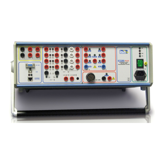
- Page 1 DOC.SIE62153 DATE: 08/12/2008 REV. 1 INSTRUMENT DRTS.3 PLUS FOR TESTING PROTECTIVE RELAYS, ENERGY METERS AND TRANSDUCERS...
- Page 2 Doc. SIE62153 Rev. 1 Page 2/24 REVISIONS SUMMARY VISA PAGE DATE 08/12/2008 Issued Lodi...
-
Page 3: Table Of Contents
....................................14 NCLOSURE 3.17 A .................................... 14 CCESSORIES 3.18 W ..............................14 EIGHT AND DIMENSIONS 4 DRTS.3 PLUS OPTIONS ................................15 4.1 O ..................................15 UTPUT VOLTAGE 4.2 O ......................15 PTIONAL CURRENT AND VOLTAGE MEASUREMENTS 4.3 H ................................15 RECISION MODEL 4.4 B... -
Page 4: General
Medium and High voltage networks. As compared to the former DRTS.3, the DRTS.3 PLUS version generates 15 A instead of 12.5 A. The test bench is housed in a case 3 U high, that contains: the power supply, the interface circuits, the control boards, the voltage and current amplifiers. -
Page 5: Options
Page 5/24 1.2 Options There are many options available for DRTS.3 PLUS: they are described in detail on chapter 4. 1.3 TDMS, the software for DRTS.3 PLUS All controls of the instrument are performed by the software TDMS, which is described in... -
Page 6: Applicable Standards
Rev. 1 Page 6/24 2 APPLICABLE STANDARDS The test set DRTS.3 PLUS and optional modules conform to the EEC directives regarding Electromagnetic Compatibility and Low Voltage instruments. 2.1 Electromagnetic Compatibility Directive no. 2004/108/EC. Applicable Standard : EN61326-1 + A1 + A2. -
Page 7: Characteristics Of The Unit
- Connect DRTS.3 PLUS to the portable PC, using the supplied cable; - Connect DRTS.3 PLUS to the relay that is to be tested. The input trip contacts can be either clean or with voltage, polarized using the optional DC voltage output, or the DC voltage of the site;... -
Page 8: Three Phase Current Generator
Doc. SIE62153 Rev. 1 Page 8/24 - Electrical drawings; - Diagnostic information, failure area, intervention procedures. 3.2 Three phase current generator - Three independent current sources, with a common neutral. - Type of connection: safety banana sockets. - For each output, a light turns on when the output is applied. - Output ranges, and corresponding power and resolution. -
Page 9: Fourth Voltage Output V4
Doc. SIE62153 Rev. 1 Page 9/24 RANGE OUTPUTS CONNECTION VOLTAGE POWER Z MAX RESOLUT. (VA) (Ohm) DIRECT 0…125 1.9 mV DIRECT 0…125 1.9 mV 190 µV DIRECT 0…12,5 19 µV DIRECT 0…1 2 IN SERIES 0…250 3.8 mV 2 IN PARALLEL 0…125 1.9 mV OPTIONAL 300 V OUTPUT... -
Page 10: Angles
Doc. SIE62153 Rev. 1 Page 10/24 . Zero-sequence component VO of the other three voltages V1, V2 V3. Via software the output can be selected to be: VO = (V1+V2+V3)/3 or VO = (V1+V2+V3)/1.73 (bolded stays for vector sum). Note that with last two selections the zero sequence component is limited to 125 V (or 300 V if the optional range is available). -
Page 11: Low Voltage Outputs
Doc. SIE62153 Rev. 1 Page 11/24 3.7 Low voltage outputs The purpose of these low voltage outputs is to allow testing newest protection relays with low voltage inputs, and to control the external boosters, thus providing the following features: . to increase the power output, or: . -
Page 12: Auxiliary Outputs
Doc. SIE62153 Rev. 1 Page 12/24 Timer range: 0 - 999,999.9999 s (277 hours); resolution: 0.1 ms. In cycles: 0 to 50,000,000 cycles (50 Hz), or 0 to 60,000,000 cycles (60 Hz); resolution: 0.005 cycles (50 Hz). Timer accuracy: 0.025% of the measure ± 0.1 ms, for input changes lasting more than 1 ms. Event recording, at the maximum frequency of 1 kHz;... -
Page 13: Transient Files Reproduction
PC by the same serial interface; . The PC examines the results, performs calculations and then displays them to the operator. - During the execution of the test DRTS.3 PLUS is self controlled and does not depend on the serial communication. -
Page 14: Power Supply
- Case: Aluminum, with carrying handle. The instrument may be operated in the horizontal or vertical positions. 3.17 Accessories The following items are supplied with the DRTS.3 PLUS : . Protection bag; . Mains supply cable; . Serial and USB cables;... -
Page 15: Drts.3 Plus Options
Doc. SIE62153 Rev. 1 Page 15/24 4 DRTS.3 PLUS OPTIONS The first five options are to be specified at order. 4.1 Output voltage The output voltage can be up to 300 V instead of 125 V; specifications are given in the voltage outputs paragraph. -
Page 16: Battery Simulator
Max. error for std. DRTS.3 0,25 0,27 Infinite PLUS, % Max error for DRTS.3 PLUS - 0,125 0,135 0,55 Infinite HP, % 3) The rated power accuracy applies for currents greater than 0,1 A and voltages greater than 10 V. -
Page 17: Iec61850 Option; Code Pii80156
Doc. SIE62153 Rev. 1 Page 17/24 - Output accuracy: ± 1% of the regulated value ± 0.1% of the full scale, with load of 25% to 100%. - Gradient accuracy: ± 1% of the nominal, with a minimum of ±200 mV/s. - Self protected in case of an overload greater than 100 W. -
Page 18: Relay Connection Cables; Code Zii15156
Doc. SIE62153 Rev. 1 Page 18/24 With the option are also provided two ETHERNET cables: one for the connection to a switch on the Station bus; the other one for the direct connection to the relay. The option is exclusive of external boosters option. This option is to be specified at order. -
Page 19: Sha-6 Energy Meters Universal Scanning Head; Code Zii20162
Doc. SIE62153 Rev. 1 Page 19/24 GPS SYNCHRONIZER PULSE START/STOP 1 pps PULSE INTERVAL (seconds) LOCKED GPS ANTENNA T0,5A 250V PULSE 100-240V~ 50/60Hz 5W GPS front and rear view 4.8 SHA-6 energy meters universal scanning head; code ZII20162 SHA-6 is a scanning head that eases the test of energy meters. It is an universal scanning head because it can be used both with LED impulse electronic meters and Ferraris rotating disk meters;... -
Page 20: In2-Cdg Current Booster For 1 Arated Relays And For The Cdg Relay Of Ge; Code Zii99156
ZII99156 With DRTS.3 PLUS the full power of 100 VA is available only at the current of 15 A. This is good for the test of relays with the nominal current of 5 A; if relays are rated 1 A the available power can be not adequate to perform the test. - Page 21 Doc. SIE62153 Rev. 1 Page 21/24 There are two instances where the option can be necessary: . Generating a current or voltage into a device that is also taking a signal from the mains; . Synchronising two test sets to the mains, and then using them to test line differential relays.
-
Page 22: Three Phase Current Amplifier And Two Voltage Amplifier Amiv-66
. To control six voltages, so that it is possible to have 6 currents and 6 voltages at the meantime. The connection between DRTS.3 PLUS and AMIV-66 is made by a control cable to be connected to the 23 way connector. -
Page 23: Two Phase Voltage Generator
Doc. SIE62153 Rev. 1 Page 23/24 5.2.2 Two phase voltage generator - Two independent voltage sources, with a common neutral. - Type of connection: safety banana plugs. - Output ranges, and corresponding power and resolution of AMIV-66 alone. RANGE OUTPUTS CONNECTION VOLTAGE POWER... -
Page 24: Enclosure
Doc. SIE62153 Rev. 1 Page 24/24 - Power consumption: . at rest: less than 100 W; . maximum load: 500 W. 5.2.4 Enclosure - Instrument: half rack; 3U high. - Case: aluminium, with carrying handle. 5.2.5 Accessories supplied with the unit - Protective plastic bag.
Need help?
Do you have a question about the DRTS.3 PLUS and is the answer not in the manual?
Questions and answers