
Related Manuals for ISA T2000


Summary of Contents for ISA T2000
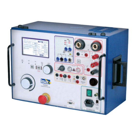
- Page 1 DATE: 04/10/20011 DOC.SIE10110 REV.6 T2000 TEST SET for testing CT’s, PT’s, primary injections and relay tests GlobalTestSupply www. .com Find Quality Products Online at: sales@GlobalTestSupply.com...
-
Page 2: Table Of Contents
DOC. SIE10110 Rev. 6 Page 3 of33 1 INTRODUCTION ............................... 4 2 APPLICABLE STANDARDS ............................7 3 CHARACTERISTICS ..............................8 3.1 F ................................8 OREWORD 3.2 M ..............................8 AIN GENERATOR 3.2.1 High AC current ............................... 8 3.2.2 Low AC current ..............................8 3.2.3 Low DC current .............................. -
Page 3: Introduction
. With the current booster: primary tests, up to 2000 A; with the very high current booster option, up to 4000 A. The basic T2000 function is to generate current and voltages, as requested by the type of test to be GlobalTestSupply performed, that is selected on the LCD screen by means of the multi-function knob. - Page 4 WINDOWS versions. The ease of operation has been the first goal of T2000: this is why the LCD is graphic, and so large. With it, the dialogue in MENU mode is made easy. Besides, all T2000 outputs relevant to the selected test are continuously measured, and output values are displayed, with no extra effort to the operator.
- Page 5 DOC. SIE10110 Rev. 6 Page 6 of33 2. Optional high voltage 1200 V, instead of 3000 V (better choice for 5 A rated CT’s), to be specified at order; 3. T2000E, model with high voltage at 1200 V and the high current output power boosted to 850 VA;...
-
Page 6: Applicable Standards
DOC. SIE10110 Rev. 6 Page 7 of33 2 APPLICABLE STANDARDS The test set conforms to the EEC directives regarding Electromagnetic Compatibility and Low Voltage instruments. A) Electromagnetic Compatibility: Directive no. 2004/108/EC. Applicable Standard : EN61326-1 + A1 + A2. EMISSION - EN 61000-3-2: Harmonic content of power supply. -
Page 7: Characteristics
3.1 F OREWORD T2000 incorporates a generator with six outputs. When an output is generated, also all other outputs are present at sockets, unless for the high AC voltage, that can be generated only if it is selected and confirmed by a key. -
Page 8: Low Dc Current
DOC. SIE10110 Rev. 6 Page 9 of33 RANGE CURRENT OUTPUT LOAD RECOVERY A AC OUTPUT POWER TIME TIME STEADY 15 min 4 min 1000 STEADY 15 min 1000 2) NOMINAL POWER 60 VA RANGE CURRENT OUTPUT MAX. TEST RECOVERY A AC OUTPUT POWER DURATION... -
Page 9: High Ac Voltage
DOC. SIE10110 Rev. 6 Page 10 of33 - Type of waveform: R-C discharge; polarity: positive. - Current range: from 0 to 10 A peak. - Repetition rate: a pulse every 3 s. - Output connection: two safety sockets. 3.2.5 High AC voltage - Type of generator: variable transformer and high voltage transformer. -
Page 10: Timer
DOC. SIE10110 Rev. 6 Page 11 of33 3.4 T IMER The electronic digital timer has a fully automatic stop, both for make and break of the input, that can be either a clean contact or a contact under voltage. All selections are menu-driven via the multi-function knob. - Page 11 DOC. SIE10110 Rev. 6 Page 12 of33 measured without saturation. For example, on the 800 A output the measuring range is up to 999 A. Actually, the test set will not generate more than 800 A, as the test is stopped by the software, that indicates overload, and on the display currents more than 800 A will not be shown.
-
Page 12: Phase Angle
DOC. SIE10110 Rev. 6 Page 13 of33 OUTPUT RANGE RESOLUTION ACCURACY HIGH AC CURRENT 19.99 A 20 mA ± (0.5% + 50 mA) 199.9 A 200 mA ± (0.5% + 400 mA) 999 A ± (0.5% + 1 A) LOW AC CURRENT; 1.999 A 1 mA ±... -
Page 13: Other Measurements
DOC. SIE10110 Rev. 6 Page 14 of33 3.5.3 Other measurements Starting from the above measurements, the test set can compute derived measurements, according to test selection. The following is the list of available measurements. For all of them the following range and resolution applies;... -
Page 14: Voltage Measurement
DOC. SIE10110 Rev. 6 Page 15 of33 - Metering temperature coefficient: ± 0,05%/°C of the value ± 0,02%/°C of the range. - Possibility to display the current waveform. 3.6.2 Voltage measurement - Two inputs: 10 V or 600 V, AC or DC - Range, resolution and accuracy: see tables below. -
Page 15: Display
DOC. SIE10110 Rev. 6 Page 16 of33 For other parameters, the accuracy is the sum of voltage, current and angle accuracies, as applicable. PARAMETER , DC INPUTS DERIVED FORMULA UNITS FROM POWER, W Iext, Vext P= I*V RESISTANCE, R Iext, Vext R = V/I With CT or VT or PT selection, the measurement follows the selected test. -
Page 16: Menu Selections
The specification of TDMS is given in a separate document. When the PC is connected, settings can also be created and transferred into T2000 using TDMS. The following table summarizes all tests and the corresponding performances. - Page 17 DOC. SIE10110 Rev. 6 Page 18 of33 LEVEL1 LEVEL 2 LEVEL 3 LEV. 4 FUNCTION Normal (default) Measures the time delay from test START to TEST Test CONTROL mode STOP (internal, external). Trip + pulse time Measures the time delay from test START to STOP (internal, external), and the duration of STOP.
- Page 18 DOC. SIE10110 Rev. 6 Page 19 of33 LEVEL LEVEL LEVEL LEVEL FUNCTION TIMER Stop Timer stops when the current of the main generator is interrupted. STOP NO-NC- Timer stops when the STOP input is detected. (def.t) EDGE (def.t) External STOP input Normally Open or Normally Closed or Both (EDGE).
-
Page 19: Transformers Selection
DOC. SIE10110 Rev. 6 Page 20 of33 LEVEL1 LEVEL LEVEL 3 FUNCTION METERS (continued) Other None (default) No extra measurement displayed external Active power P; W Reactive power (AC) Q; VAr Impedance module Z, Ohm φ, ° Impedance argument Active impedance R, Ohm component... - Page 20 DOC. SIE10110 Rev. 6 Page 21 of33 TEST TEST INPUT DATA CONN. OUT CONN. IN MEASUREMENTS DESCRIPTION Ratio Voltage mode - I primary; High/Low V AC CT primary 1) High / Low VAC out; N. 1 - I secondary to CT to low or high 2) Low V in;...
-
Page 21: Connection Cables
DOC. SIE10110 Rev. 6 Page 22 of33 TEST TEST INPUT DATA CONN. OUT CONN. IN MEASUREMENTS DESCRIPTION Ratio; polarity V primary in kV; High V AC 1) High VAC (primary) N. 8 V secondary; to VT primary secondary 2) V in (secondary); Connection LL, LN to V in 3) Phase shift ;... -
Page 22: Other Characteristics
DOC. SIE10110 Rev. 6 Page 23 of33 5. N. 2 High voltage connection cables, 4 m long, 5 kV, with earth screen. Terminated on one side with an HV connector, and on the other side with a safety banana plug. 6. -
Page 23: Optional High Voltage Output 1200 V; Codes Pii30110 (Supply 230 V) Or Pii40110 (Supply 110 V)
- N. 2 High current connection cables, 95 sq. mm, 0.5 m long. Terminated on one side with an high current connector to T2000, and on the other side with a ring terminator. - N. 4 High current connection cables, 95 sq. mm, 4 m long. Terminated on both sides with a ring terminator. -
Page 24: Current Clamp Code Pii16102
DOC. SIE10110 Rev. 6 Page 25 of33 Two types of transit cases are available: molded and aluminum. 3.12.4.1 Molded case; code PII24102 The protection of T3000 from delivery problems is provided by this robust transit case, that features the following. - Molded-case construction;... -
Page 25: Thermal Printer Pii14102
The following sketch shows the connections between T2000, the BU2000 INTERPOSING MODULE and the transformers (up to 4). - Page 26 The other transformers, BU2000 AUX, have only the supply cable. All cables are 20 m long. Connections from T2000 to the BU2000 INTERPOSING MODULE are: . The variable AC voltage output (not isolated from the mains), that performs the fine current adjustment;...
- Page 27 Above characteristics apply for power supply of 230 V. For the power supply of 115 V, with the optional T2000 model code PII20110, codes are different, and performances are as follows. Performance reduction follows the limitation to the supply current.
- Page 28 DOC. SIE10110 Rev. 6 Page 29 of33 Each option is provided with a connection cable having the following characteristics: - Number of conductors: 2. - Conductors cross section: 95 sq. mm. - Conductors type: high flexibility. - Conductors length: 2.8 m. - Weight, including the screw-driven clamps: 8.5 kg.
-
Page 29: High I Dc Module Pii13102
The high DC current module allows the measurement of the low contact resistance of high voltage breakers or of joints. The option is connected to the high AC current output of T2000; the current measurement is connected to the low DC current measurement input; the drop voltage is connected to the low voltage measurement input. -
Page 30: Ft/1000 Current Filter, Code Pii16093
Rev. 6 Page 31 of33 To perform the test, the T2000 output is connected to the overhead line to be tested, that is put out of service. The purpose of the SU3000 optional device is to protect the operator, during the connection and during the operation, against possible high voltage spikes. - Page 31 - One current clamp to connect T2000 to the local earth system. B) Voltage measurement - One cable for the connection of T2000 to one voltage spike, 50 m long, 2,5 sq. mm cross section, wound on a wheel. Terminated with a safety banana connector for the connection to the voltage spike, and with a safety socket for the connection to T2000.
-
Page 32: Protections
DOC. SIE10110 Rev. 6 Page 33 of33 PROTECTIONS - If the test set is not connected to the ground, the test set does not allow for power generation, and warns the operator with a diagnostic message. - Fuse on the mains supply. - At power-on, a diagnostic sequence controls: .
Need help?
Do you have a question about the T2000 and is the answer not in the manual?
Questions and answers