
Related Manuals for ISA T1000 PLUS


Summary of Contents for ISA T1000 PLUS
- Page 1 DATE: 29/11/2011 DOC.SIE91093 REV.7 SINGLE PHASE RELAY AND MINIATURE CIRCUIT BREAKERS TEST SET MOD. T1000 PLUS PowerMeterStore 1.877.766.5412 www. Shop for Power Metering products online at:...
-
Page 2: Table Of Contents
2.12.7 TD1000 PLUS 15Hz model: higher power at low frequency, code PII93093..........31 2.12.8 FT/1000 current filter, code PII16093 ......................32 2.12.9 SHA-1000 scanning head for T1000 PLUS and T3000, code PII43102 ............. 32 2.12.10 Outputs transducer and connection cables for low level signal relays............. 33 3 PROTECTIONS ................................ -
Page 3: Applicable Standards
DOC. SIE91093 Rev. 7 Page 4 of 37 APPLICABLE STANDARDS The test set conforms to the EEC directives regarding Electromagnetic Compatibility and Low Voltage instruments. A) Electromagnetic Compatibility: Directive no. 2004/108/EC. Applicable Standard : EN61326-1 + A1 + A2. EMISSION - EN 61000-3-2: Harmonic content of power supply. -
Page 4: Introduction
Page 5 of 37 INTRODUCTION The relay test set mod. T1000 PLUS is suited for the testing and adjustments of Low Voltage Miniature Circuit Breakers and of the following types of relays. Distance protection (phase by phase) (21, *) ... - Page 5 The ease of operation has been the first goal of T1000 PLUS: this is why the LCD is graphic, and so large. With it, the dialogue in MENU mode is made easy. Besides, all T1000 PLUS outputs are continuously measured, and output values are displayed, with no extra effort to the operator.
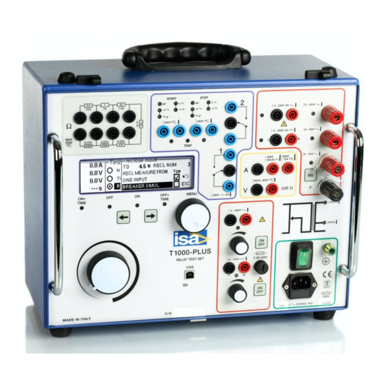
- Page 6 DOC. SIE91093 Rev. 7 Page 7 of 37 The instrument is housed in a transportable aluminium box, which is provided with removable cover and handles for ease of transportation. The test set is shown here below. NOTE: WINDOWS is a trademark of MICROSOFT Inc. PowerMeterStore 1.877.766.5412 www.
-
Page 7: Characteristics
DOC. SIE91093 Rev. 7 Page 8 of 37 CHARACTERISTICS 2.1 MAIN GENERATOR The main generator has three outputs: currents, voltage AC, voltage DC. The following specification applies to the separate usage of these outputs. It is possible to use them at the meantime, provided that the total maximum load is not exceeded. -
Page 8: Main Ac Voltage
DOC. SIE91093 Rev. 7 Page 9 of 37 A AC OUTPUT POWER TIME TIME STEADY 10 min 0.75 STEADY 10 min STEADY 10 min - Power selection: via menu. - Connection: four high power sockets, with safety protections, marked: 0; 10 A; 40 A; 100 A. 2.1.2 Main AC voltage - The main AC voltage is isolated from the main AC current. -
Page 9: Other Features Of Main Outputs
DOC. SIE91093 Rev. 7 Page 10 of 37 RANGE VOLTAGE LOAD LOAD RECOVERY REDUCED V DC OUTPUT CONSUMPTION TIME TIME POWER STEADY 60 (120) 60 (120) STEADY - Type of DC voltage: unregulated, via diode bridge rectifier and capacitor. - Connection: two safety banana sockets. 2.1.4 Other features of main outputs - Zero crossing control. - Page 10 DOC. SIE91093 Rev. 7 Page 11 of 37 - Possibility to phase shift the auxiliary AC voltage output with respect to: the main current and the main AC voltage. The phase angle reference is the auxiliary voltage. Phase shifter characteristics: .
- Page 11 DOC. SIE91093 Rev. 7 Page 12 of 37 V1 PRE-FAULT V1 FAULT FAULT ANGLE V1 FAULT PRE-FAULT ANGLE I1 FAULT Figure 2 – Prefault voltage - Possibility to define the duration TPF of pre-fault generation, after test start, prior to generating fault values.
-
Page 12: Auxiliary Dc Voltage
DOC. SIE91093 Rev. 7 Page 13 of 37 2A) Underfrequency 2B) Overfrequency Figure 3 - Frequency relay test waveform - Possibility to test frequency rate of change relays. Frequency ROC range: from 0.01 to 99.99 Hz/s. The frequency change stops at 40 or 70 Hz. 2.3 AUXILIARY DC VOLTAGE - The auxiliary DC voltage output, V DC aux, is isolated from the main AC current and voltage and... -
Page 13: Timer
DOC. SIE91093 Rev. 7 Page 14 of 37 2.4 T IMER The electronic digital timer has a fully automatic start and stop, both for make and break of the input, which can be either a clean contact or a contact under voltage. All selections are menu-driven via the multi-function knob. -
Page 14: Test Control
In the first operating mode, T1000 PLUS is connected as follows: Trip command to the STOP input; Close command to the START input. As Close is detected, the test set automatically applies current with the programmable reclaim time delay TD. -
Page 15: Auxiliary Contacts
DOC. SIE91093 Rev. 7 Page 16 of 37 FAULT TRIP (STOP) CLOSE (START) TIME MEASUREMENTS Figure 4: Measure of Delay and Close times The second operating mode refers to pole mounted CB’s. In this mode, there is only one signal coming from the device under test: the position of the CB. -
Page 16: Outputs Measurement
DOC. SIE91093 Rev. 7 Page 17 of 37 - Delay range with respect to test start: from 0 to 999.99 s. - Maximum time error between current and make/break contact: 2 ms. - Contacts range: 5 A; 250 V AC; 120 V DC 2.7 O UTPUTS MEASUREMENT 2.7.1 Current and voltage... -
Page 17: Phase Angle
DOC. SIE91093 Rev. 7 Page 18 of 37 299.9 V 300 mV ± (1% + 300 mV) 130 V DC 19.99 V 15 V 10 mV ± (0.5% + 100 mV) 199.9 V 100 mV ± (0.5% + 200 mV) 240 V DC 19.99 V 15 V... -
Page 18: External Inputs Measurement
DOC. SIE91093 Rev. 7 Page 19 of 37 The following is the list of available measurements. For all of them the following range and resolution applies; the accuracy is the sum of voltage, current and possibly angle accuracy. PARAMETER RANGE; X RESOLUTION IS THE MEASURED ENTITY 0 –... -
Page 19: Voltage Measurement
DOC. SIE91093 Rev. 7 Page 20 of 37 2.8.2 Voltage measurement - Maximum input voltage: 600 V, AC or DC - Range, resolution and accuracy: see table below. RANGE RANGE RESOLUTION ACCURACY CHANGE 19.99 V AC 15 V 10 mV ±... -
Page 20: Display
The specification of TDMS is given in a separate document. When the PC is connected, settings can also be created and transferred into T1000 PLUS using TDMS. The flux diagram of menu selections can be found in Appendix 1. PowerMeterStore 1.877.766.5412... - Page 21 Momentary Generation lasts until the ON button is pressed External Generation starts upon reception of the START input: this allows synchronising T1000 PLUS. Timed Max time Generation lasts for the pre-set time duration. Max time 999 s. T delay...
- Page 22 DOC. SIE91093 Rev. 7 Page 23 of 37 LEVEL LEVEL LEVEL LEVEL FUNCTION TIMER Start INT (default) Timer starts when ON or ON+TIME are activated START/ and outputs generated. STOP NO-NC- After ON or ON+TIME, timer starts on the external EDGE input.
- Page 23 DOC. SIE91093 Rev. 7 Page 24 of 37 LEV. LEV. LEV. LEVEL LEVEL 5 FUNCTION Range 65 (default) ; 130 ; 260 V. VAC/ Mode Fault (default) The auxiliary AC voltage is adjusted by the dedicated con- knob, and is always present, independently by test start. trol If the auxiliary voltage should be applied along with the main current or voltage, go to next selection.
- Page 24 DOC. SIE91093 Rev. 7 Page 25 of 37 METERS Internal Units of I Normal If selected, current values are displayed in A. I/IN If selected, displayed values are defined as I/IN, that can be defined. Units of V Normal If selected, voltage values are displayed in V.
- Page 25 DOC. SIE91093 Rev. 7 Page 26 of 37 LEVEL1 LEVEL LEVEL 3 FUNCTION METERS Other None (default) No extra measurement displayed (continued) internal Active power P; W Reactive power Q; VAr Impedance module Z, Ohm φ, ° Impedance argument Active impedance R, Ohm component...
-
Page 26: Other Characteristics
DOC. SIE91093 Rev. 7 Page 27 of 37 LEVEL1 LEVEL 2 LEVEL 3 LEVEL 4 FUNCTION RESULTS Delete Selected result(s) All results Save to address 1..10 Saves current settings to X CONFIGU- Settings RATION Restore address 1..10 Restores settings from X Restore default Restores default settings Language... - Page 27 DOC. SIE91093 Rev. 7 Page 28 of 37 . Ground connection cable: 2 m, yellow/green, terminated with crocodile clamp. - Dimensions: 380 (W) * 300 (D) * 240 (H) mm. - Weight: 19 kg. PowerMeterStore 1.877.766.5412 www. Shop for Power Metering products online at:...
-
Page 28: Options
These cables, together with the standard ones, allow for the connection to the relay under test to all test set sockets. 2.12.3 Transit case, code PII17093 The transit case allows delivering T1000 PLUS with no concern about shocks up to a fall of 1 m. PowerMeterStore 1.877.766.5412 www. -
Page 29: E" Model: Higher Ac Voltage Outputs, Code Pii92093
DOC. SIE91093 Rev. 7 Page 30 of 37 2.12.4 “E” model: higher AC voltage outputs, code PII92093 In this model, AC voltage outputs are higher than in the standard version. - Main AC voltage output. Available power and duty cycle: see table below. RANGE VOLTAGE LOAD... -
Page 30: Td1000 Plus 15Hz Model: Higher Power At Low Frequency, Code Pii93093
DOC. SIE91093 Rev. 7 Page 31 of 37 Last, the steady voltage output power is increased from 30 VA to 50 VA. When the current range is selected, the output measurement is A, and not V. NOTE: as with the main current source, this is a low voltage, high current generator: the current is a function of the load, and is to be adjusted after the relay is connected. -
Page 31: Ft/1000 Current Filter, Code Pii16093
The option includes: - The support that allows keeping the scanning head in front of the energy meter: maximum height 175 mm; - The cable, 2 m long, from the scanning head to T1000 PLUS or T3000; PowerMeterStore 1.877.766.5412 www. -
Page 32: Outputs Transducer And Connection Cables For Low Level Signal Relays
Page 33 of 37 - The power supply transformer, for the power of 220 V AC, to supply the scanning head. - Two safety banana plugs for the connection to T1000 PLUS or T3000. Specifications: - Supply voltage: 11 to 30 V DC;... - Page 33 DOC. SIE91093 Rev. 7 Page 34 of 37 Connection cables characteristics: 2 m long; Connections, ABB: round connector to the Outputs transducer; two BNC connectors for V and I; one RJ-45 connector for the supply. Connections, THYSENSOR: round connector to the Outputs transducer; one RJ-45 connector for V and I outputs.
-
Page 34: Protections
DOC. SIE91093 Rev. 7 Page 35 of 37 PROTECTIONS - Fuse on the mains supply. - At power-on, a diagnostic sequence controls: . Key microprocessor board components; . Auxiliary supply voltages. If something is wrong, the operator is alerted by a message. - Thermal sensor on the main and auxiliary transformers. -
Page 35: Appendix 1: Auxiliary Ac Output Features Comparison
DOC. SIE91093 Rev. 7 Page 36 of 37 APPENDIX 1: AUXILIARY AC OUTP UT FEATURES COMPARISON The following tables summarize the auxiliary AC output features of the different test models. RANGE RANGE CURRENT POWER @ 15 Hz, CURRENT POWER @ > 40 Hz, A @ >... -
Page 36: Appendix 2: Menu Selections Flux Diagram
Normal (default) Trip + pulse time Test mode Reclose mode Maintained (default) Fault injection Momentary External TEST CONTROL Timed Output power OFF delay Save Don’t save (default) Automatic at trip Confirm at trip Auxiliary contacts Manual N.O.-N.C.-EDGE Internal (default) Clean – 24 V – 80 V Start Count External...
Need help?
Do you have a question about the T1000 PLUS and is the answer not in the manual?
Questions and answers