ISA STS 4000 Manual

ISA STS 4000 Manual

For the test of ct, vt and pt
Table of Contents

Advertisement

STS + TD 5000 FAMILY
S
PECIFICATIONS
for the test of CT, VT and PT
DOCUMENT No. SIE10175, Rev. 14, «Date»
PowerMeterStore
1.877.766.5412
www.
.ca
Shop for Power Metering products online at:

Advertisement

Table of Contents
loading

Summary of Contents for ISA STS 4000

  • Page 1 STS + TD 5000 FAMILY PECIFICATIONS for the test of CT, VT and PT DOCUMENT No. SIE10175, Rev. 14, «Date» PowerMeterStore 1.877.766.5412 www. Shop for Power Metering products online at:...
  • Page 2: Table Of Contents

    ABLE OF CONTENTS SPECIFICATIONS ................................1 GENERAL ................................7 APPLICABLE STANDARDS ............................17 CHARACTERISTICS ...............................19 ................................19 OREWORD ..............................19 AIN GENERATOR 3.2.1 High AC current ............................20 3.2.2 High DC current ............................20 3.2.3 Low AC current ............................21 3.2.4 Low DC current ............................
  • Page 3 4.22 PII44175) ....................73 IGITAL HERMO YGROMETER CODE 4.23 RCTD PII47175) ............... 74 REACTOR FOR MOTORS AND GENERATORS MEASURES PROTECTIONS ..............................76 PowerMeterStore 1.877.766.5412 www. Shop for Power Metering products online at:...
  • Page 4 Copies, reprints or other reproductions of the content or of parts of this publication shall only be permitted with ISA prior written consent.
  • Page 5: General

    STS 5000 listed tests It is the same as STS 5000, unless the high AC and DC current generators. High AC STS 4000 current tests can be performed using the BUX 3000 option; micro-Ohm metering is not available STS 3000 light It allows performing Tan(δ) tests with the option TD 5000...
  • Page 6: Table 4 - Voltage Transformers Tests

    The following table lists the tests performable by the Voltage Transformers: Test STS 5000 STS 4000 STS 3000 light Ratio Ratio Electronics Burden Voltage Withstand Polarity Check Tangent δ TD 5000 TD 5000 TD 5000 Ratio IEC61850-9-2LE Table 4 - Voltage Transformers tests The Ratio test for Not-Conventional transformer with the option IEC61850-9-2LE is available only in remote control mode, using the PADS software.
  • Page 7 The test Ratio IEC61850-9-2LE can be executed only in remote mode, using the PADS software. Tests are performed in accordance with the following standards: • IEC EN 60044-1 • IEC EN 60044-2 • IEC EN 60044-5 • IEC EN 60044-7 •...
  • Page 8: Table 8 - Optional Modules
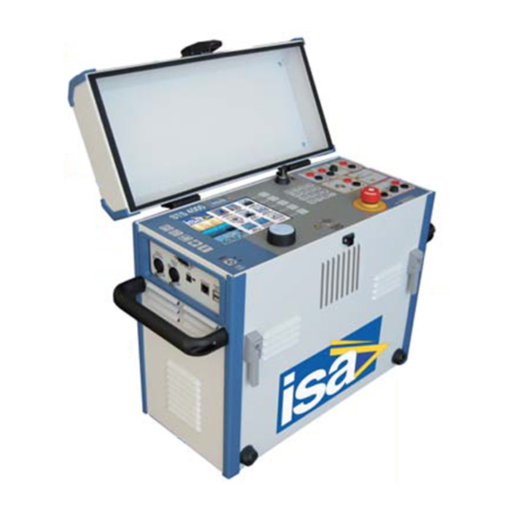
    The following table lists the optional modules enhance the STS features: Item Option Code Description PII17175 Transit Cases PII19175 They allow transporting the device PII51175 PII10176P PADS license PII10176T PC Remote control of the test set PII10176F When the Remote Safety Switch is connected and enabled, it avoids any Remote Safety Switch PII42175 current or voltage generation from pressing START/STOP button on the STS...
  • Page 9 The basic STS function is to generate current and voltages, as requested by the type of test to be performed; only one test at a time. The test is selected on the LCD screen by means of the multi-function knob. Test results are kept in local memory or in a USB card, and can be transferred to a PC later, along with settings.
  • Page 10: Figure 1 - Sts 5000

    The following image exhibits the STS 5000 as an example of the model of the family, with the protection cover lifted: Figure 1 - STS 5000 PowerMeterStore 1.877.766.5412 www. Shop for Power Metering products online at:...
  • Page 11: Figure 2 - Test Set Front Panel

    The following image exhibits the front panel: Figure 2 - Test set front panel The following table lists all the elements of the front panel: ITEM Component Cover Help. Pressing it, the screen displays the information related to the test performed Open file.
  • Page 12: Table 10 - Frontal Panel Components (2/2)

    ITEM Component 16-keys alpha-numeric keyboard Emergency push-button with lock-in AC voltage and current output, up to 6 A – 70 V or 3 A - 140 V, fuse protected. Fuse rating: FF 6.3 A 250 V. The LED turns ON when it is active DC current output, up to 6 A, fuse protected.
  • Page 13: Figure 3 - Left Panel Components

    Alarm output connector, for the light strobe with buzzer option PII43175 Remote start input connector, for the remote push-button option PII42175 USB connection only for ISA diagnostic Flash disk connector for the local test results saving or for moving the local test results from the local memory ETHERNET connection to the PC.
  • Page 14: Figure 4 - Right Panel Components

    The following image exhibits the side panel on the right: Figure 4 - Right panel components The following table lists the elements of the right panel: ITEM Component Ground connection socket Resettable power supply automatic fuses, rated 16 A 240 V Power supply plug Power supply connection to external optional modules (TD5000, BUX3000, STCS Booster 20 A DC) High voltage output connectors, rated 2 kV AC...
  • Page 15: Applicable Standards

    PPLICABLE STANDARDS The test set conforms to the EEC directives regarding Electromagnetic Compatibility and Low Voltage instruments. The following table lists the standards related to the EMC Directive, 2004/108/EC: Standard Title Requirement Electrical equipment for measurement, control EN 61326 and laboratory use. EMC requirements. General requirements Electromagnetic compatibility (EMC) - Part 3-2: IEC EN 61000-3-2:...
  • Page 16: Table 14 - Standards Related To The Lv Directive

    The following table lists the standards related to the LV Directive, 2006/95/EC: Standard Title Requirement For a pollution degree 2: dielectric rigidity 1.4 kV AC, 1 minute The rigidity is 4600 V AC 1 minute between the high voltage output and the rest of inputs and outputs. •...
  • Page 17: Characteristics

    HARACTERISTICS Foreword STS incorporates a generator with six outputs. When an output is generated, there is voltage also on all other outputs, unless for the high AC voltage. The generator is made of an electronic type D switching amplifier, followed by a power transformer, which adapts the suitable current or voltage output.
  • Page 18: High Ac Current

    3.2.1 High AC current The output is available only on the STS 5000. The following table lists the output characteristics, at 50 to 60 Hz and supply of 230 V: Current output Output power Load time [VA] 4,800 3,780 2,560 1,940 900 (15 min) 1,300...
  • Page 19: Low Ac Current

    3.2.3 Low AC current The output is available on the STS 5000 and STS 4000. Type of generator: not controlled low AC current. The output current can be manually adjusted using the front panel controls, and measured via the test set current meter.
  • Page 20: High Ac Voltage

    3.2.5 High AC voltage The output is available on the STS 5000 and STS 4000. The high AC voltage output is coming from the same transformer as high AC or DC current, but an HV switch inside the test set isolates it.
  • Page 21: Low Ac Voltage

    3.2.6 Low AC voltage The output is available on the STS 5000 and STS 4000. Type of generator: not controlled low AC voltage. The output voltage can be manually adjusted using the front panel controls, and measured via the test set voltage meter.
  • Page 22: High Power Output To The External Modules

    3.2.7 High power output to the external modules The output is available on all models of the STS family. The output feeds the external modules type TD 5000, BUX 2000, BUX 3000, STLG, STCS Booster 20 A DC. The following table lists the output characteristics: Insulation Output not insulated from the mains supply Output voltage...
  • Page 23: Outputs Measurement

    Outputs measurement The display shows the following: • The High AC current • The High DC current • The High AC voltage • The corresponding output current All of them are shown in their evolution during the test. The display shows also the selected measurement inputs. True rms for AC outputs Type of measurement DC component for DC outputs...
  • Page 24: Timer

    Timer The STS 5000 and STS 4000 allow to measure a device timing, using a special input. At the test start with voltage or current generation, a timer is started; the timer stops when the relay has tripped. It is also possible to stop the timer when the injected current is stopped by the intervention of the device under test.
  • Page 25: Other Measurements

    Other measurements Starting from the internal and external measurements, the test set computes derived measurements, according to the test selection. The following table lists the available measurements (the accuracy is the sum of voltage, current and possibly angle accuracy): Parameter Derived from Formula Units...
  • Page 26: Table 37 - Resistance Test: Range And Accuracy

    For the resistance test it is possible to perform it with four wires, with the two available DC sources, or with two wires, using the 10 V measurement input. The following table lists the corresponding range and accuracy (the maximum resistance is 20 kΩ): Source Resistance range...
  • Page 27: Display

    Display The following image exhibits the STS display: Figure 5 - STS display The following table lists the main features of the display: Pixel Light LCD type View area 640 x 480, colors Backlight 132 x 99 mm Table 40 - Main features of the display Test control Test control: by the START / STOP pushbutton.
  • Page 28: 3.10 Menu Selections

    3.10 Menu selections The following image exhibits the Home page of the test set of the Test Plan Editor: Figure 6 – Home page The menu is entered pressing the knob and selecting the item moving the knob. The Test Plan Editor is an innovative and advanced software module, allowing the operator to define and plan a sequence of tests.
  • Page 29: Figure 8 - "Current Transformers/Header And Nominal Values" Page (Tab Description)

    The following image exhibits the “Power Transformers – Header and Nominal Values” page (tab Description), visible at first time in which entering this section, or pressing the button “Header/Nominal Values”: Figure 8 - "Current Transformers/Header and Nominal Values" page (tab Description) The following image exhibits the tab “Nominals”...
  • Page 30: Figure 10 - "Current Transformers/Header And Nominal Values" Page (Tab Tolerances)

    The following image exhibits the tab “Tolerances”: Figure 10 - "Current Transformers/Header and Nominal Values" page (tab Tolerances) The page allows setting the tolerances for each of the available tests. If the tolerance is exceeded, the deviation is shown in the test result table. After having set this basic information, pressing the shortcut “Edit Test Plan”...
  • Page 31: Figure 12 - "Cts - Ratio Polarity And Burden Current Method" Page

    For instance, the following image exhibits the “CTs – Ratio Polarity and Burden Current Method” page: Figure 12 - "CTs – Ratio Polarity and Burden Current Method" page As the test programming is finished, pressing the shortcut “Exit” by the side of the icon, it is possible to come back to the test selection table.
  • Page 32: Table 41 - Current Transformers Tests (1/4)

    The following table lists the Current Transformers tests: Test Test description The ratio measurement is performed applying high current to the CT primary, and measuring the CT secondary current. The burden can be by-passed, or left in series for the measurement: in this instance, the voltage drop is measured.
  • Page 33: Table 42 - Current Transformers Tests (2/4)

    Test Test description The resistance (not impedance) is measured connecting the low DC current source to the winding or burden, and measuring the test current and the voltage drop. Input parameters are the following: • The nominal resistance • The connected output •...
  • Page 34: Table 43 - Current Transformers Tests (3/4)

    Test Test description The test is performed connecting the high AC current source to the primary side, and connecting the CT secondary side to the low voltage measurement. Input parameters are the following: • The nominal primary current and the nominal secondary voltage, from which the program computes the nominal ratio •...
  • Page 35: Table 44 - Current Transformers Tests (4/4)

    Test Test description Ratio measure and currents polarity for Not Conventional Transformers. The test is executed applying current to the primary side and reading the corresponding “Sample Values”. The test is executed using the test set remote connection with the PC, using the PDS program.
  • Page 36: Table 45 - Voltage Transformers Tests (1/2)

    The following table lists the Voltage Transformers tests: Test Test description The ratio measurement is performed applying high voltage to the VT primary, and measuring the VT secondary voltage. Input parameters are the following: • The nominal primary and secondary voltage, from which the program computes the nominal ratio •...
  • Page 37: Table 46 - Voltage Transformers Tests (2/2)

    Test Test description The test is performed connecting the high AC voltage source to the primary side, and measuring the induced secondary voltage with the optional PLCK polarity sensor. Input parameters are the following: Polarity • The test voltage Check •...
  • Page 38: Table 47 - Power Transformers Tests (1/3)

    The following table lists the Power Transformers tests: Test Test description The ratio measurement is performed applying high voltage to the VT primary, and measuring the VT secondary voltage for each tap. If the STCS option is available, connection is performed via the option, and the test is completely automatic. Input parameters are the following: •...
  • Page 39: Table 48 - Power Transformers Tests (2/3)

    Test Test description The test is performed connecting the high AC voltage source between the CT secondary cabling and the ground or between the CT primary and secondary. Input parameters are the following: • Maximum test current (with automatic switch-off) •...
  • Page 40: Table 49 - Power Transformers Tests (3/3)

    Test Test description The test is performed using the TD 5000 optional module, and then connecting the high AC voltage source to test target. Displayed parameters are the following: • Test type (1): Where the HV output is applied: in case of a specific device under test (CT, VT, PT or bushing), the options are displayed •...
  • Page 41: Table 50 - Circuit Breakers Tests

    The following table lists the Circuit Breakers tests: Test Test description The contact resistance test is performed using the high DC current output. The test set measures the contact resistance down to the µΩ range. With the same selection, and different generators, it is also possible to measure higher resistances.
  • Page 42: Table 51 - Resistances Tests (1/2)

    The following table lists the Resistances tests: Test Test description The contact resistance test is performed using the high DC current output. The test set measures the contact resistance down to the µΩ range. With the same selection, and different generators, it is also possible to measure higher resistances.
  • Page 43: Table 52 - Resistances Tests (2/2)

    Test Test description The step and touch voltages test is performed applying current between the ground grid and the auxiliary ground spikes, and measuring the step or touch voltage with the test probes. With the STLG option, the current generation is performed using an overhead line to connect to the remote ground.
  • Page 44: Table 53 - Other Possible Tests

    The following table lists other possible tests: Test Test description The selection allows injecting the test parameter, and measuring the relay threshold and trip delay. The tests are feasible using the trigger input logic, or by stopping the test when the current disappears (M.V. CB). With the option BUX 2000 and BUX 3000 it is possible to perform high current tests.
  • Page 45: Standard Connection Cables (Long Cables Code Pii16175 And Extra Long Cables Code Pii57175)

    Connection cables differ somewhat as a function of the type of test set. The following table lists cables provided: STS 3000 Item Description STS 5000 STS 4000 light No 1 Mains supply cable, 2 m long No 1 Grounding cable, 6 m long, 6 mm , terminated on one side with...
  • Page 46: 3.12 Other Characteristics

    800 A output or on the options BUX 2000 and BUX 3000 400 (H)x450 (W)x230 (D) mm STS 5000 weight: 29 kg Dimensions STS 4000 weight: 22 kg STS 3000 light weight: 16 kg • User manual, in English, Italian, French and Spanish •...
  • Page 47: Options

    PTIONS Transit cases (code PII17175, PII 19175, PII51175) The following image exhibits a transit case: Figure 13 - Transit case This option applies to all STS models. There are more types of transit cases: • one for the STS • one for TD 5000 •...
  • Page 48: Pads Licence (Code Pii10176P, Pii10176F, Pii10176T)

    PADS licence (code PII10176P, PII10176F, PII10176T) The software PADS allows connecting to the PC all models of the STS. Software features are the following: • To download from the test set test results and settings, and to save them into a file •...
  • Page 49: Remote Safety Switch (Code Pii42175)

    Remote Safety Switch (code PII42175) The following image exhibits the Remote Safety Switch: Figure 14 - Remote Safety Switch This option applies to all STS models. When the Remote Safety Switch is connected and enabled, it avoids any current or voltage generation from pressing START/STOP button on the STS only.
  • Page 50: Stcs Automatic Connection Windings Module (Code Pii12175)

    STCS automatic connection windings module (code PII12175) This option applies to STS 5000 and STS 4000. It is applicable when it is necessary to perform one of the following tests on PT: • Ratio • Winding resistance • Short-circuit impedance •...
  • Page 51: Stcs Power Generator Booster 20 A Dc (Code Pii32175)

    STCS power generator Booster 20 A DC (code PII32175) This option applies to STS 5000 and STS 4000 and must be connected to the STCS, which controls the option itself. The STCS Booster 20 A DC allows to perform winding resistance tests up to 20 A DC on a PT.
  • Page 52: Stde Residual Magnetization Removal Module (Code Pii27175)

    STDE residual magnetization removal module (code PII27175) This option allows neutralizing the residual magnetization of the power transformer core after the winding resistance test. The connection to STS is mandatory. The following image exhibits the STDE option: Figure 19 - STDE option The principle of the option is to apply a DC voltage with alternate polarity to the transformer winding, following the IEEE 62-1995 standard.
  • Page 53: Stsa Surge Arrester (Code Pii46175)

    The following image exhibits the STSA Surge Arrester: Figure 20 - STSA Surge Arrester This option applies to STS 5000 and STS 4000. The option limits voltage surges generated at the DC Voltage input measurement if, during the winding resistance test, the circuit is erroneously opened.
  • Page 54: Table 60 - Max Test Currents And Durations (230 V) For Bux 3000

    The option avoids wasting power on the connection cables, by putting the power transformers as close as possible to the test object. This approach is particularly useful when the test is performed on CTs in the field, which are some meters tall.
  • Page 55: Current Clamp (Code Pii16102)

    The following table lists the maximum test currents and durations for power supply of 110 V for BUX 2000: Test current Output power On duration [VA] Infinite 1,000 1,500 1,300 2,400 Table 63 - Max test currents and durations (110 V) for BUX 2000 BUX 3000 and BUX 2000 characteristics are the following: •...
  • Page 56: Plck Polarity Checker (Code Pii41175)

    4.11 PLCK Polarity Checker (code PII41175) This option applies to STS 5000 and 4000 models. The following image exhibits the PLCK option: Figure 23 - PLCK option The PLCK Polarity Checker has three colored LED: • Pass (GREEN).Indicates the right polarity •...
  • Page 57: Power Factor Correction Module (Code Pii85175)

    The STLG option characteristics are the following: • Input: form STS 5000, via the booster connector • Output current ranges: 11, 22, 35, 55, 105 A AC. Corresponding no-load voltages: 540, 270, 160, 108, 55 V • Output current connection: via high current sockets •...
  • Page 58: Stlg Large Station (Code Pii88175)

    4.14 STLG large station (code PII88175) The following image lists the kit elements: Element Description Photo • STLG Transport case with wheels PII19175 • PII80175 Standard cable kit PII75175 with case • N°3 cable connection studs (diameter 20 mm) PII72175 STSG •...
  • Page 59: Table 66 - Kit Elements (2/2)

    Element Description Photo N°2 exible cables, cross section 10 mm 50 m long, for Additional the connection of the power output, mounted on the power cables cable-winding with wheels N°10 cables, 2,5 mm , 100 m long, each mounted on Measure cables its reel;...
  • Page 60: Stsg Safety Grounding Module (Code Pii71175)

    4.15 STSG safety grounding module (code PII71175) This option applies to STS 5000 and STS 4000; it is used with the STLG option, to increase the operator safety. The following image exhibits the STSG option: Figure 25 - STSG option During tests, STLG is connected to the out of service overhead line to be tested.
  • Page 61: Cylindrical Studs

    4.15.1 Cylindrical studs The following table lists the studs for the STSG option: Stud code Drawing Characteristics max short circuit current: 0.5 s: 33.5 kA PII72175 max short circuit current: 1.0 s: 23.7 kA max short circuit current: 0.5 s: 42.0 kA PII73175 max short circuit current: 1.0 s: 29.6 kA...
  • Page 62: Ground Grid Test Accessories Kit (Code Pii76175)

    The following image exhibits the Ground Grid Test Accessories Kit: Figure 26 - Ground Grid Test Accessories Kit This option applies to STS 5000 and STS 4000 models. The following table lists the elements of the Ground Grid Test Accessories Kit:...
  • Page 63: Current Clamp Meter (Code Pii79175)

    4.17 Current Clamp Meter (code PII79175) The following image exhibits the current clamp meter: Figure 27 – Current Clamp Meter When it is necessary to use the STSG and STLG options to execute the test, the options are connected to a transmission line.
  • Page 64: Foldable Trolley (Code Pii18175)

    4.18 Foldable Trolley (code PII18175) The following image exhibits the Foldable Trolley: Figure 28 - Foldable Trolley This option applies to all STS models. The trolley eases the handling of STS + TD 5000. The trolley hosts both instruments and the HV cable for TD 5000. When not used, it can be folded, to minimize the volume.
  • Page 65: Figure 30 - Power Supply On The Side

    The High Voltage generator TD 5000 performs the measurement of the Tan(δ), of the dissipation factor and of the capacitance of a transformer or of a bushing, at the frequency of the mains or in a wide frequency range. The measurement is performed by the module, which is equipped with a patented measurement circuitry;...
  • Page 66: Figure 32 - Hv Output On The Front Panel

    The following image exhibits the HV output on the front panel: Figure 32 - HV output on the front panel It is possible to see that there is one HV connector, and there are two metering inputs. This allows the Tan(δ) measurements of all points with one connection.
  • Page 67: Table 73 - Frequency Characteristics Of Td 5000

    The following table lists the frequency characteristics of TD 5000: Range Accuracy 15÷500 Hz 50 ppM typical; 100ppM maximum Table 73 - Frequency characteristics of TD 5000 The connections of the TD 5000 are the following: • HV panel for the connection of the double shielded safety cable •...
  • Page 68: Table 75 - Cables Supplied With Td 5000

    The following table lists the connection cables supplied with TD 5000 (they come as standard with the test set; however, they can also be ordered separately): Cable Characteristics No 1 yellow-green 6 m long, for the ground connections. Terminated with terminator on one side, and connection cable with a clamp on the other side No 2 yellow-green...
  • Page 69: Table 76 - Parasitic Capacitances

    The following table lists the parasitic capacitances which exist in a three winding (two secondary) power transformer, in a two winding (one secondary) power transformer and in a bushing transformer: Transformer Scheme Terms Three winding (two • H = high voltage terminal secondary) •...
  • Page 70: Cap-Cal Reference Capacitor (Code Pii40175)

    The following image exhibits the connection of the CAP-CAL to the TD 5000: Figure 34 - Connection of the CAP-CAL to the TD 5000 A calibration certificate is issued by ISA laboratory and it is supplied together the CAP-CAL. PowerMeterStore 1.877.766.5412...
  • Page 71: Stoil Cell For The Insulating Oil Check (Code Pii13175)

    4.21 STOIL cell for the insulating oil check (code PII13175) This option applies to TD 5000, to perform Tan(δ) test of the PT oil. The following image exhibits the STOIL option: Figure 35 - STOIL option Cell characteristics are the followings. •...
  • Page 72: Figure 37 - Rctd Option

    The following table lists the main characteristics: Characteristic Value (-10÷+60) °C Temperature range (-50÷+250) °C with an external sensor External temperature sensor RTD Ni1000/6180 ppM, not included Temperature measurement accuracy ±0.4 °C Humidity measurement range (5÷95)% RH Resolution of humidity measurement 0.1% ±2.5% RH Accuracy of humidity measurement...
  • Page 73 The reactor has a standard cable kit (code PII48175) and the following table lists them: Cable Characteristics Scheme 6 m long, 6 mm terminated with N. 1 ground cable terminator and clamp N. 1 safety cable To STS; 10 m long, 2x0,5 mm N.
  • Page 74: Protections

    ROTECTIONS The protections of the STS are the following: • If the test set is not connected to the ground, the test set does not allow for power generation, and warns the operator with a diagnostic message and a fixed led light •...
  • Page 75: Table 80 - Revisions

    EVISIONS The following table lists the revisions of the document: Date Description January 2011 First issue October 2011 Modified HV outputs, tanδ, low voltage, STCS Revised all options February 2012 Added the oil test cell January 2013 Final revision April 2013 Improved the description of TD 5000 February 2014 Added the PLCK and the RCTD options...
  • Page 76 IST OF FIGURES 1 - STS 5000 ................................12 IGURE 2 - T ............................13 IGURE EST SET FRONT PANEL 3 – L ............................15 IGURE EFT PANEL COMPONENTS 4 - R ............................16 IGURE IGHT PANEL COMPONENTS 5 - STS ................................
  • Page 77 IST OF TABLES 1 - STS F ..............................7 ABLE AMILY MODELS 2 - D STS F ......................7 ABLE IFFERENCES AMONG THE AMILY MODELS 3 - C ............................ 7 ABLE URRENT RANSFORMER TESTS 4 - V ........................... 8 ABLE OLTAGE RANSFORMERS TESTS .............................
  • Page 78 53 – O ............................46 ABLE THER POSSIBLE TESTS 54 - C ..........................47 ABLE ABLES PROVIDED WITH THE UNIT 55 - O STS ........................48 ABLE THER CHARACTERISTICS OF THE 56 – T ........................49 ABLE RANSIT CASE MAIN CHARACTERISTICS 57 - T ............................

This manual is also suitable for:

Sts 3000 lightSts 5000

Table of Contents