Table of Contents
Advertisement
Quick Links
This publication, including all photographs, illustrations and
software, is protected under international copyright laws, with all
rights reserved. Neither this manual, nor any of the material
contained herein, may be reproduced without the express written
consent of the manufacturer.
The information in this document is subject to change without
notice. The manufacturer makes no representations or warranties
with respect to the contents hereof and specifically disclaims any
implied warranties of merchantability or fitness for any particular
purpose. Further, the manufacturer reserves the right to revise this
publication and to make changes from time to time in the content
hereof without obligation of the manufacturer to notify any person
of such revision or changes.
Trademarks
IBM, VGA, OS/2, and PS/2 are registered trademarks of
International Business Machines.
Intel, Pentium, Pentium-II, Pentium-III, MMX, and Celeron are
registered trademarks of Intel Corporation.
Microsoft, MS-DOS and Windows 95/98/NT are registered
trademarks of Microsoft Corporation.
Sound Blaster and SB-Link are trademarks of Creative Technology
Ltd.
PC-cillin and ChipAway Virus are trademarks of Trend Micro Inc.
AMI is a trademark of America Megatrends Inc.
A3D is a registered trademark of Aureal Inc.
Gamut is a registered trademark of Formosoft International Inc.
SuperVoice is a registered trademark of Pacific Image
Communications Inc.
MediaRing Talk is a registered trademark of MediaRing Inc.
WordPerfect is a registered trademark of Corel Corporation Ltd.
Other names used in this publication may be trademarks and are
acknowledged.
Copyright © 1999
All Rights Reserved
M765MRT, Version 1.2A
i6T/May 1999
Advertisement
Table of Contents

Related Manuals for PC Chips M765MRT


Summary of Contents for PC Chips M765MRT
- Page 1 MediaRing Talk is a registered trademark of MediaRing Inc. WordPerfect is a registered trademark of Corel Corporation Ltd. Other names used in this publication may be trademarks and are acknowledged. Copyright © 1999 All Rights Reserved M765MRT, Version 1.2A i6T/May 1999...
- Page 2 Federal Communications Commission (FCC) This equipment has been tested and found to comply with the limits for a Class B digital device, pursuant to Part 15 of the FCC Rules. These limits are designed to provide reasonable protection against harmful interference in a residential installation.
-
Page 3: Table Of Contents
Table of Contents Chapter 1 Introduction............1 Key Features..................2 Slot-1 Processor Support...............2 Socket-370 Processor Support............2 Memory Support................2 Expansion Slots................2 Onboard IDE channels..............3 Power Supply and Power Management.........3 Sound System................3 Onboard I/O Ports................3 Hardware Monitoring..............4 Fax/modem DAA Module.............4 Onboard Flash ROM..............4 Bundled Software................4 Dimensions..................4 Package Contents................5 Optional Accessories..............5... - Page 4 Table of Contents Install Other Devices................22 Floppy Disk Drive...............22 IDE Devices.................22 Internal Sound Connections............23 Analog Audio................23 Digital Audio Connection............23 Expansion Slots................24 Add-In Card Options..............25 LAN Wake Up................25 SB-Link..................25 Chapter 3 BIOS Setup............26 Introduction..................26 Running the Setup Utility..............26 Standard CMOS Setup Page............28 Advanced Setup Page..............29 Advanced Chipset Setup Page............31 Power Management Setup Page............32...
- Page 5 Table of Contents Demo...................43 Appendix A: Corel WordPerfect Suite 8 ......A1 Welcome to Corel WordPerfect Suite 8 .........A2 Installing Corel WordPerfect Suite 8 ..........A6 Learning how to use Corel WordPerfect Suite 8 ......A9 Support and Services ..............A13 Appendix B: Gamut ............B1 Introduction ..................B2 Before Installing ................B3 Installation ..................B4...
-
Page 6: Chapter 1 Introduction
Chapter 1 Introduction This mainboard has a slot-1 processor socket for an Intel processor cartridge, and it also has a socket-370 for an Intel PPGA (Plastic Pin Grid Array) Celeron processor. You can install either one of these processors according to the power and performance requirements that you need from your system. -
Page 7: Key Features
Chapter 1 Key Features This key features of this mainboard include: Slot-1 Processor Support Pentium-III support for 450 MHz and 550 MHz clock rates Pentium-II support for 233 MHz to 450 MHz clock rates SEPP Celeron support for 266 MHz to 433 MHz clock rates ... -
Page 8: Onboard Ide Channels
Package Contents Onboard IDE channels Primary and Secondary PCI IDE channels Support for PIO (programmable input/output) modes Support for Bus mastering and UltraDMA 33 modes Power Supply and Power Management Dual connector for either AT or ATX power supply ... -
Page 9: Hardware Monitoring
Chapter 1 Hardware Monitoring Built-in hardware monitoring for CPU/system temperatures, fan speeds and mainboard voltages Supports AMI’s Desktop Client Manager (ADCM) Fax/Modem DAA Module 56 Kbps Fax/Modem DAA module Supports V.90, V.34, V.32bis, V.32, V.22bis, V.22 ... -
Page 10: Package Contents
Package Contents Package Contents Your mainboard package ships with the following items: Mainboard This User’s guide IDE cable Floppy diskette drive cable Audio ports and Game/MIDI port extension bracket Serial ports extension bracket Parallel port extension bracket ... -
Page 11: Static Electricity Precautions
Chapter 1 Static Electricity Precautions 1. Components on this mainboard can be damaged by static electricity. Take the following precautions when unpacking the mainboard and installing it in a system. 2. Keep the mainboard, and other components, in their original static-proof packaging until you are ready to install them. -
Page 12: Chapter 2 Mainboard Installation
Chapter 2 Mainboard Installation To install this mainboard into your system, follow the procedures in this chapter: Identify the mainboard components Install the correct processor Install one or more memory modules Verify that any jumpers or switches are at the correct setting ... -
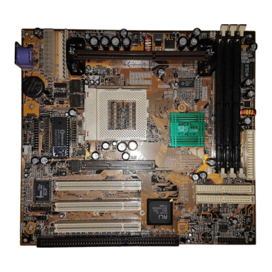
Page 13: Mainboard Components
Chapter 2 Mainboard Components Use the diagram below to identify the major components on your mainboard. Note: Some versions of this mainboard use the Intel 440 BX chipset. These boards have three DIMM slots. Some versions of this mainboard use the Intel 440 ZX chipset. These boards only have two DIMM slots. -
Page 14: Install The Processor
Install Other Devices Install the Processor This mainboard has a Slot-1 that can be installed with any Slot-1 processor cartridge including the Pentium-III, Pentium-II, and the SEPP Celeron. It also has a Socket-370 that can be installed with the Celeron processor which is shipped in a PPGA (Plastic Pin Grid Array) package. -
Page 15: Installing A Slot-1 Processor Cartridge
Chapter 2 Installing a Slot-1 Processor Cartridge 1. Locate Slot-1, FAN1, and JP4 on the mainboard. FAN1 Slot-1 with pre-installed cartridge holder. The upright arms are folded down for shipping. 2. The Slot-1 is installed with a cartridge holder. The upright struts of the cartridge holder are folded down for shipping. -
Page 16: Installing A Socket-370 Processor
Install Other Devices 5. Locate the jumper JP4. Use this jumper to select if you have installed a Slot-1 processor or a Socket-370 processor. The jumper settings are illustrated below. Selects a Socket-370 Selects a Slot-1 processor processor 6. On this mainboard, you can configure the processor by entering the correct settings in the BIOS setup utility. -
Page 17: Install Memory
Chapter 2 4. Match the pin-1 corners and insert the Celeron processor into the socket. No force is required and the processor should drop into place freely. 5. Swing the locking lever down and hook it under the catch on the side of the socket. - Page 18 Install Other Devices DIMM1 DIMM2 DIMM3 For this mainboard, you must use 168-pin, 3.3V memory modules installed with SDRAM memory chips. If you are using a processor cartridge that runs on a 100 MHz system bus, you must use memory that operates on a 100 MHz memory bus (PC-100 memory).
-
Page 19: Set The Jumpers
Chapter 2 Set the Jumpers Jumpers are sets of pins that can be connected together with jumper caps. The jumper caps change the way the mainboard operates by changing the electronic circuits on the mainboard. If a jumper cap connects two pins, we say the pins are SHORT. If a jumper cap is removed from two pins, the pins are OPEN. -
Page 20: Jumper Jp5: Clear Cmos Memory
Install Other Devices Note: Make sure that the system can provide 1A on +5VSB (+5V Standby) signal before using the Keyboard Power On function. Function Jumper Setting Disable Keyboard Power On Short Pins 1-2 Enable Keyboard Power On Short Pins 2-3 Jumper JP5: Clear CMOS Memory Use this jumper to clear the contents of the CMOS memory. - Page 21 Chapter 2 ATX-PW1 AT-PW2 FAN2 Connect the power cable from the power supply unit to the power connector on the mainboard. If you are using an AT power unit, connect it to the AT power connector PW2. If you are using an ATX power unit connect it to the ATX power connector PW1.
-
Page 22: Install The Extension Brackets
Install Other Devices Install the Extension Brackets The extension brackets are used to transmit features on the mainboard to external connectors that can be fixed to the system chassis. Follow the steps below to install the extension brackets. Note: All the ribbon cables used on the extension brackets carry a red stripe on the pin-1 side of the cable. -
Page 23: Serial Ports Extension Bracket
Chapter 2 Serial Ports Extension Bracket This bracket has two serial ports; COM1 (9-pins) and COM2 (25pins). 1. On the mainboard, locate the two headers COM1 and COM2 for this bracket. 2. Plug the two cables from the bracket into the appropriate COM1 and COM2 headers. -
Page 24: Fax/Modem Daa Module
Install Other Devices PRN1 Parallel port LPT1 Parallel Port Extension Bracket 1. On the mainboard, locate the parallel port headers PRN1 for this bracket. 2. Plug the cable from the bracket into the PRN1 header. 3. In the system chassis, remove a blanking plate from one of the expansion slots and install the extension bracket in the slot. -
Page 25: Optional Extension Brackets
Chapter 2 1. Locate the J3 modem header on the mainboard. 2. Plug the Fax/Modem DAA module into the J3 modem header. 3. Remove the blanking plate adjacent to the Fax/Modem DAA module. Line & Tel RJ11 phone Modem DAA Module jacks Modem Header Optional Extension Brackets... -
Page 26: Digital Audio Extension Bracket
Install Other Devices 1. On the mainboard, locate the J7 ATX header for this bracket. 2. Plug the cable from the bracket into the J7 ATX header. 3. In the system chassis, remove a blanking plate from one of the expansion slots and install the extension bracket in the slot. -
Page 27: Install Other Devices
Chapter 2 Install Other Devices Install and connect any other devices in the system following the steps below. Floppy Disk Drive The mainboard ships with a floppy disk drive cable that can support one or two drives. Drives can be 3.5” or 5.25” wide, with capacities of 360K, 720K, 1.2MB, 1.44MB, or 2.88MB. -
Page 28: Internal Sound Connections
Install Other Devices Install the device(s) and supply power from the system power unit. Use the cable provided to connect the device(s) to the Primary IDE channel connector IDE1 on the mainboard. If you want to install more IDE devices, you can purchase a second IDE cable and connect one or two devices to the Secondary IDE channel connector IDE2 on the mainboard. -
Page 29: Expansion Slots
Chapter 2 Note: You cannot use the J2 digital audio in connector if you have already used the SPDIF1 digital audio in/out connector to connect to a digital audio extension bracket. Expansion Slots This mainboard has one AGP slot, three 32-bit PCI expansion slots, and one 8/16-bit ISA slot. -
Page 30: Add-In Card Options
Install Other Devices 3. Remove the blanking plate from the appropriate expansion slot on the system chassis. 4. Install the edge connector of the expansion card into the slot and press it quite firmly down so that it is seated correctly. 5. -
Page 31: Chapter 3 Bios Setup
Chapter 3 BIOS Setup Introduction The BIOS setup utility stores information about your computer such as the date and time, the kind of hardware you have installed, and so on. Your computer uses this information to initialize all the components at boot up time, and make sure that everything runs smoothly. - Page 32 Chapter 3 You can use the cursor arrow keys to highlight any of the options on the Mainmenu page. Press Enter to select the highlighted option. To leave the setup utility, press the Escape key. Hold down the Shift key and press F2 to cycle through the optional color schemes of the setup utility.
-
Page 33: Standard Cmos Setup Page
Advanced Chipset Setup Page Standard CMOS Setup Page Use this page to set basic information such as the date and time, the IDE devices, and the diskette drives. Date & Time Use these items to install your system with the correct date and time Pri Master Use these items to configure devices on the... -
Page 34: Advanced Setup Page
Chapter 3 Advanced Setup Page Use this page to set more advanced information about your system. Take some care with this page. Making changes can affect the operation of your computer. Quick Boot If you enable this item, the system starts up more quickly be elimination some of the power on test routines. - Page 35 Advanced Chipset Setup Page Floppy Drive If you enable this item, your system will check the Seek diskette drives at start up time. Disable this item unless you are using an old 360K diskette drive. PS/2 Mouse Set this item to auto so that it will automatically Support detect if you are using a mouse with a PS/2 interface.
-
Page 36: Advanced Chipset Setup Page
Chapter 3 Advanced Chipset Setup Page This page lets you set some of the timing parameters for the system. Trend ChipAway This mainboard has built-in virus protection in the firmware. Use this item to enable or disable the Virus built-in virus protection. SDRAM Items The five items which define the timing for SDRAM memory are pre-installed with fixed... -
Page 37: Power Management Setup Page
Advanced Chipset Setup Page PCI 2.1 Support Enable this item to support compliance with thw PCI specification version 2.1 On Board USB Enable this item if you plan on using the USB (Universal Serial Bus) ports integrated on this Function mainboard. - Page 38 Chapter 3 Power Use this item to enable or disable the power management routines. If you enable the power Management/APM management, you can use the items below to set the power management operation. Green Monitor This item defines which power-saving mode is required to trigger the power management Power State operations of a green monitor.
-
Page 39: Pci / Plug And Play Setup Page
Advanced Chipset Setup Page LAN Resume From If you enable this item, network traffic to the Soft Off LAN adapter can resume the system from a power-saving mode or a software power down. RTC Alarm Power If you enable this item you can set an alarm on the system realtime clock that will resume the system from a power-saving mode or a software power down. -
Page 40: Load Optimal Settings
Chapter 3 PCI VGA Palette When this item is enabled, multiple VGA devices operating on different buses can handle Snoop data from the CPU on each set of palette registers on every video device. Assign IRQ for If this item is enabled, an IRQ will be assigned to the VGA graphics system. -
Page 41: Load Best Performance Settings
Advanced Chipset Setup Page Load Best Performance Settings If you select this item and press Enter a dialog box appears. If you press Y, and then Enter, the setup utility is loaded with a set of best-performance default values. The optimal default values are quite demanding and your system might not function properly if you are using slower memory chips or other kinds of low- performance components. -
Page 42: Hardware Monitor & Cpu Pnp Setup Page
Chapter 3 Serial Port2 Mode Use this item to allocate the resources of the second serial port. Under Normal, the resources are allocated to the onboard serial port. Under ASKIR or IrDA, the resources are allocated to the onboard IR port, IR Duplex Use this item to define if the optional infrared port is full-duplex or half-duplex. -
Page 43: Change Supervisor Password
Advanced Chipset Setup Page CPU Speed Use this item to set the internal clock speed of your CPU. CPU Clock Use this item to increase the clock speed of Overdrive your CPU. We recommend that you do not try to run your CPU faster than its rated speed. CPU Temperature Use this item to set the threshold temperature for the CPU. -
Page 44: Save Settings And Exit
Chapter 3 the system will flash an N in the dialog box. Press Enter to skip the device and proceed to the next device. Press Y, then Enter to tell the system to auto-detect the device. Save Settings and Exit Highlight this item and press Enter to save the changes that you have made in the setup utility and exit the setup program. -
Page 45: Chapter 4 Software & Applications
The IDE Bus Master Drivers allows the system to properly manage the IDE channels on the mainboard. You only need to install an IDE driver if you are running Windows 95. Windows 95 – D:\IDE\M765MRT\WIN95\SETUP.EXE Windows NT4.0 – D:\IDE\M765MRT\NT40 USB Driver The USB Driver allows the system to recognize the USB ports on the mainboard. -
Page 46: Sound Driver
Chapter 4 Sound Driver The Sound driver allows the system to generate optimal sound effects. This driver is available for: DOS & Windows 3.x – D:\SOUND\DRIVER\8738AM\DOS- Windows 9X – D:\SOUND\DRIVER\8738AM\W95-98 Windows NT – D:\SOUND\DRIVER\8738AM\NT40 There is also an Audio application program available for: ... -
Page 47: Using The Pci Sound Pro Application
Introduction Using the PCI Sound Pro Application 1. Before you install the PCI Sound Pro drivers, make sure your Operating System has been installed, otherwise the PCI Sound Pro might be detected as “Other device” by the device manager of your OS. 2. -
Page 48: Speaker Position
Chapter 4 Speaker Position Set up your speakers similar to the following figure to get the best audio result. Mixer Setup There is a 4-speakers option in the Volume Control of the Mixer when you are setting up the PCI Audio Application. Click on the 4 SPK icon to enable this option.
Need help?
Do you have a question about the M765MRT and is the answer not in the manual?
Questions and answers