Table of Contents
Advertisement
Quick Links
Advertisement
Table of Contents

Subscribe to Our Youtube Channel
Related Manuals for Trikdis SP131


Summary of Contents for Trikdis SP131
- Page 1 SECURITY MODULE SP131 User manual...
-
Page 2: Table Of Contents
CONTENTS SAFETY REQUIREMENTS ..........................3 DESCRIPTION OF THE SECURITY MODULE SP131 .................... 4 ........................... 6 OMPATIBLE MODULES ..........................7 ECHNICAL PARAMETERS ............................7 ACKAGE CONTENT ..........................8 ODULE COMPONENTS ......................... 8 ERMINAL BLOCK DESCRIPTION ............................8 IGHT INDICATION INSTILLATION ..............................9 .......................... -
Page 3: Safety Requirements
Safety requirements Please read this manual carefully before using the security module SP133. Security module should be installed and maintained by qualified personnel, having specific knowledge regarding the functioning of GSM devices and safety requirements. The device must be disconnected from external power supply source before starting device installation. -
Page 4: Description Of The Security Module Sp131
Description of the security module SP131 The module SP131 is an intruder and fire alarm control panel with an integrated GSM modem which can transmit event messages through GPRS connection or SMS messages to central monitoring station as well as SMS messages can be sent to user mobile phone. - Page 5 Event messaging to OS Android phone or tablet with GSM/3G modem Module can be set to send a special format SMS messages to OS Android device with installed app Trikdis SP131 Control. The app Trikdis SP131 Control will convert your OS Android device into user-friendly, informative and cost effective (depends on cost of SMS) console for security system control and management.
-
Page 6: Compatible Modules
Auto ARM function The function applied for protecting against accidental system disarming. If the security system is disarmed with a phone call and during the time for entry into the premises none of the secured zones are violated, the module will automatically rearm to previous ARM / STAY / SLEEP mode by itself. -
Page 7: Technical Parameters
Operating environment From -10 C to 50 C when relative air humidity is 80 % at +20 C Dimensions 103 x 71 x 33,5 mm Package content Security module SP131 1 pc. Battery connection cable 1 pc. Resistors 2,2 kΩ... -
Page 8: Module Components
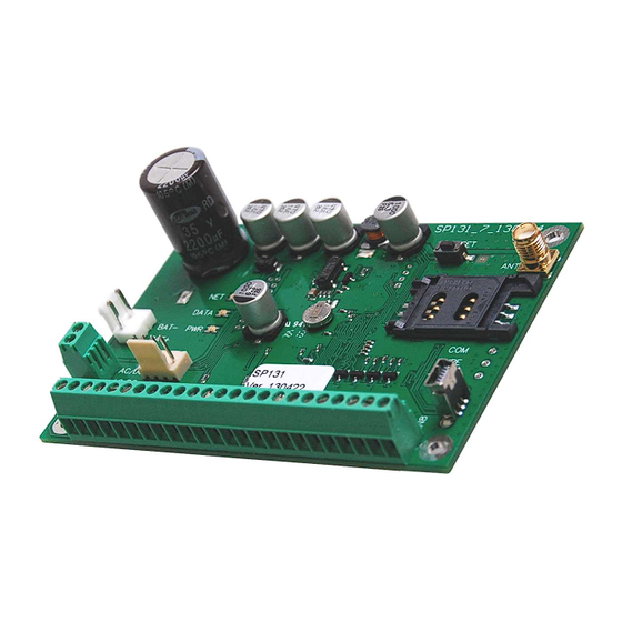
Module components 1. Light indication of network and operation 2. Terminal for backup power 3. Terminal block for power wires 4. RESET button 5. GSM antenna connector 6. SIM card holder 7. USB socket for configuring the module 8. Two wire data bus terminals 9. -
Page 9: Instillation
8. Turn on the main power supply. Security system will send E305 (system reset) event message. If there are additional modules wired to YEL/GRN and MCI of the module SP131, security system will send R333 (Expansion Module Restore) event message in addition to E305. In set time interval E760 (PING) event message will be sent to central monitoring station IP receiver. -
Page 10: Wiring Diagram
Wiring diagram Typical zone circuits Normally closed circuit (NC) Normally open circuit (NO) Normally open (NO) or normally closed circuit (NC) with end of line resistor (EOL = 2K2) - Page 11 PGM connections 2-wire smoke detectors 4-wire smoke detectors In order to connect a two-wire smoke detector it should be connected to ZN8 input, which must be set: a) as Fire zone, b) input target for two-wire smoke detectors must be on (Set IN8 as 2-Wire box must be checked in System Options >...
-
Page 12: Setting Up Operating Parameters Of The Module
4. Set the preferred language in the Language option field. Press the button OK. 5. Choose the command Devices in the menu bar and make sure it is set to SP131/SP133. Default parameters will be shown in SPconfig windows and the lower bar will show info about module. -
Page 14: Connecting To A Computer Via Gprs
Connecting to a computer via GPRS In order to be able to program the module SP131 remotely via GPRS, several conditions has to be met: 1. Inserted SIM card in to the module has to be with enabled GPRS service. For activating GPRS service you have to contact your network provider. -
Page 15: Spconfig Software
SPconfig software It is recommended to use the default parameters set in the module when developing your alarm system and change them only then there is a need and knowledge that they mean. Setting the main characteristics of security module In the System Options directory of SPconfig the common parameters of the module can be set. -
Page 17: User Code Management
User code management The directory Users is for entering telephone numbers, names and user codes of the users who will be able to control the security system. User number Section for entering a user Section for entering name of the user. The name of the code user will be included in SMS message Section for entering user telephone number which will be allowed to... -
Page 18: Inputs
Inputs Zone properties can be set in Settings tab of Inputs directory. By double-clicking left mouse button on an input row a table will appear, intended for setting parameters of the necessary input. The module will not react to disturbances in a protected zone if their duration will Enable Alarm reporting be shorter than set in this section... -
Page 19: Sms Text
SMS text SMS text can be set in Reporting tab of Inputs directory. PGM outputs PGM outputs parameters are configured in Outputs directory. Every output mode is described in annex. Note: If there is PGM output set to Remote Control by DIAL mode, Remote Arm/Disarm by call and warning call functions will be disabled. -
Page 20: Cms Reporting
CMS Reporting GPRS and/or SMS reporting to central monitoring station parameters of the module can be set in CMS Reporting directory. The exact values of parameters should be provided by a person in charge of the central monitoring station and by GSM/GPRS provider. -
Page 21: User Reporting
User Reporting Reporting to the user GSM phone parameters can be set in User Reporting directory. Note: CMS reporting has priority over User reporting. Messages are sent to monitoring station first and only then to the user. If there is a need for messages to be sent only to the user, CMS Reporting has to be disabled in Communication type section. -
Page 22: Event Summary
Bus modules The Bus modules directory presents the list of expansion modules connected to YEL/GRN data bus and registered on SP131 module, for example, keypad or input expanders. MCI Bus Modules The MCI Bus Modules directory presents the list of expansion modules which can be connected to MCI data... -
Page 23: Events Log
3. Press Start FW Update [F9] button to initiate firmware update of the module. To start firmware update press reset at the back of the SP131 module and wait until Wait until end of process bar will be filled. Reset the module. -
Page 24: Security System Control
Security system control Control by SMS Security system can be controlled by SMS, but only some parameters of the module can be changed by SMS. To change all parameters of the module, use the program SPconfig. In order to change the desired parameter of the module, it is necessary to send an SMS message with the following syntax: PSW[Password] [Command code]... -
Page 25: Control By The Keypad Protegus
Control by the keypad Protegus ARM. Note. If there is zone alarm, security system cannot be armed. [ 1 2 3 4 ] Enter a User code with a keypad. After entering a User code the time countdown Exit Delay for leaving the premises and closing the door will start. The keypad indicator [ARM] will start flashing until ARM mode turns on, after that indicator [ARM] will be constantly on until DISARM. - Page 26 5. Bypass function. It will be possible to ARM the security system, though the bypassed zone will be violated. Zone bypass can be done only for one arm/disarm period. ] + [ 1 2 3 4 ] + [ 1 2 ] + [ Before arming the security system touch the key [ ] on the keypad and enter the User code.
-
Page 27: Control By The Keypads Of Paradox
Control by the keypads of Paradox 1. ARM. Note. If there is zone alarm, security system cannot be armed. [1234] Enter a User code with a keypad. After entering a User code the time countdown Exit Delay for leaving the premises and closing the door will start. The keypad key [ARM] will start flashing until ARM mode turns on, after that [ARM] key will be constantly on until DISARM. - Page 28 7. Master code. Master code can be changed, but cannot be deleted. + [1234] + [01] + [XXXX] + [XXXX] + [ENTER] + [CLEAR] + [CLEAR] Press the key and enter the Master code (default - 1234). The key will start to flash and the key [1] will light up.
-
Page 29: Annex 1. Zone Types
ANNEX 1. Zone types Zone type Description of reaction ON/OFF Security system can be armed and disarmed by breaking the input circuit. The security system will arm after the specified duration of time (Exit Delay), during which one the secured premises can be leaved. Set by default on ZN7, EOL;... -
Page 30: Annex 2. Pgm Output Types
ANNEX 2. PGM output types PGM output Output signal Bell Output for connecting a sound-emitting (siren) device. The continuous or pulsed signal is formed if security system is alarmed. Set by default on PGM1. Fire Alarm Alarm Buzzer Output for connecting a sound emitting device. The pulsed signal is formed during the time for leaving the premises (Exit Delay). - Page 31 Battery OK Output for connecting an indicator which informs about powering of the module from the battery. Battery OK Battery Fail Remote Control by DIAL Output which can be controlled by phone call. DIAL Pulse Time Pulse mode: DIAL DIAL Level mode: ARM/DISARM Output for connecting an indicator which informs about system state.
-
Page 32: Annex 3. Warranty And Liability Restrictions
Manufacturer is in no way associated with GSM/GPRS/Internet service providers (operators), thus UAB “TRIKDIS” is in no way responsible for any defects in Device operation if they have occurred because of the loss of GSM/GPRS/Internet connection, or because of other defects in the service provider network.
Need help?
Do you have a question about the SP131 and is the answer not in the manual?
Questions and answers