Advertisement
Quick Links
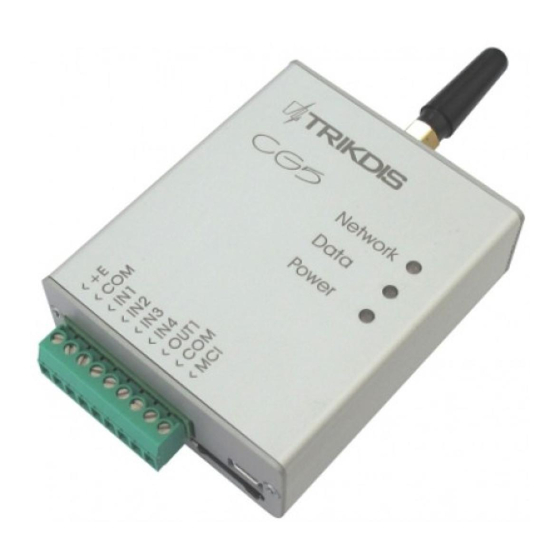
GSM module CG5
(v.2.XX)
Installation manual
Safety requirements
Liability restrictions. Please read this manual carefully before using the security module CG5.
Security module CG5 shall be installed and maintained by qualified personnel, having specific knowledge
regarding the functioning of GSM devices and safety requirements. The device must be disconnected from
power supply source before starting device installation.
Module CG5 shall be mounted in places with restricted access and in safe distance from any sensitive
electronic equipment. The device is not resistant to mechanical effects, dampness and hazardous chemical
environment.
Liability restrictions
When buying the Device, the Buyer agrees that the Device is a part of a security system of premises, which sends messages
about security system status. The Device, when installed, does not diminish the probability of burglary, fire, intrusion or other
breach of premises.
UAB "TRIKDIS" is not responsible for burglary, fire or any other breach of Buyer's and/or User's premises and is not liable for
any direct or indirect damages incurred thereof.
When buying the Device, the Buyer agrees that the Device supplied by UAB "TRIKDIS" fully meets his requirements for
intended use.
UAB "TRIKIDIS" provides no guarantees that the Device shall function as declared if the Device is installed and used not
according to its original purpose, user manual and relevant electronic and technical conditions.
UAB "TRIKDIS" is in no way associated with GSM/GPRS/Internet service providers (operators), thus UAB "TRIKDIS" is in no way
responsible for any defects in Device operation if they have occurred because of the loss of GSM/GPRS/Internet connection, or
because of other defects in the service provider network.
UAB "TRIKDIS" has no control and is not responsible for the prices and marketing of network services provided by the
GSM/GPRS/Internet service providers.
UAB "TRIKDIS" is not responsible if GSM/GPRS/Internet services are not provided to the Buyer and/or User of the Device or
were cancelled and any direct or indirect damages were incurred thereof.
UAB "TRIKDIS" is not responsible for any direct or indirect damages incurred by the Buyer and/or User of the Device due to loss
of electricity.
UAB "TRIKDIS" is not liable if Device firmware versions were not updated by the Buyer and/or the User on time.
User manual of the Device can contain technical inaccuracies, grammatical or typographical errors. UAB "TRIKDIS" reserves the
right to correct, update and/or change information in the installation manual.
Package contents
The Module CG5
GSM antenna of straight type
Two-sided adhesive tape (10 cm)
GSM module CG5
CG5 is a device, which sends SMS messages with text to 1-4 mobile phones about disturbing the security
system of the premises. Features:
Sends SMS messages if one of the input circuits is broken at least
−
Every SMS message contains exact event time stamp
−
Supports texts about events are set with Lithuanian, Latin or Russian characters
−
User can be alerted about the sending of SMS messages with a phone call
−
Power-supply voltage control
−
LED indication about device operation status and GSM signal strength
−
Output can be controlled with an SMS message
−
Operating parameters can be set with a program CG5config or by sending SMS messages
−
Description of Device Operation
Module CG5 can be set to operate in one of the two modes:
a) Constant input control mode (24 h). After the control panel has changed the state of its PGM
output, this causes module input circuit breaking. Module CG5 immediately sends an SMS
message with pre-set content to a mobile phone. When the input circuit state restores, the
module will send an SMS message about this event. General wiring diagram is given in Fig. 1.
b) Switched input control mode (Control panel). When operating in this mode, input MCI functions
as an input status controller. While input MCI is connected with COM, disturbances in inputs
IN1...IN4 are ignored and SMS messages about them are not sent. After the MCI input circuit has
been broken, the module CG5 will send an SMS message informing that the inputs are Under
Control and disturbances in inputs IN1...IN4 circuits will no longer are ignored. When circuits of
the inputs IN1...IN4 are broken, module will send messages about these events.
Output OUT1 can be used to connect a siren. Siren is activated when the module CG5 registers an event.
Switching off mode Under Control deactivates the siren as well. Switching on the mode Under Control is
followed by one short siren signal and switching off – by two.
Module CG5 has five NC / NO / EOL=2.2 kΩ type inputs. When operating in 24 h mode, module MCI input is the
fifth 24 hour managed input, and when operating in Control panel mode it operates as a controller for the
other four inputs.
SMS messages can be sent to 1-4 mobile phones. It is possible to configure how User can be alerted and what
type of messages should be sent to every phone.
Module can 1-9 times call to every chosen phone from the list to alert Users about events in security system.
Call duration is 20 seconds.
SMS messages will include an event time stamp, when the module internal clock is set with an SMS message.
Output OUT1 is open collector type and can commutate direct voltage up to 30 V and current up to 1 A. If the
output is set to Siren mode, after disturbing the input circuits the output will be activated for two minutes.
Sending interval for periodic "Test" messages is from 1 to 240 hours. Text of Test message can be customized.
Module monitors power supply voltage. When voltage drops below 11,5 V, a message informing about the
drop in voltage is sent. Message is also sent when voltage restores to 12,6 V.
Technical parameters
Power supply voltage
DC 12,6 ± 3 V
Used current
60–100 mA (stand-by mode)
Up to 250 mA (transmitting mode)
GSM modem frequency
850 / 900 / 1800 MHz
Sending messages
Text SMS messages up to 4 mobile phones
Memory
Up to 60 messages
Inputs
4+1, NC / NO / EOL=2.2 kΩ
Output
1 OC type, commutating up to 30 V voltage and current up to 1 A
Test message sending interval
0 ÷ 240 h
Setting configuration
Through the USB port or with SMS messages
Operating environment
From -10 °C to 50 °C, with relative air humidity 80% when +20 °C
Dimensions
65 x 79 x 25 mm
Trikdis, JSC
Draugystės st. 17,
LT-51229 Kaunas
Email: info@trikdis.lt
www.trikdis.lt
1 pc.
1 pc.
1 pc.
Module components
Terminal block description
Contact
Description
+E
+12 V power supply clamp
COM
Common clamp
IN1...IN4
Input clamps (NC type)
OUT1
Output clamps (OC type)
COM
Common clamp
MCI
Programmable input clamp
Light indication
LED
Operation
Indicator Network
Green flashing
displays connection with
Green ON
GSM network status
Yellow flashing
Yellow ON
Indicator Data displays
Green ON
data buffer status
Red ON
Red flashing
Red flashing rapidly
Indicator Power displays
Green flashing
all power supply status,
functioning of
Yellow flashing
microcontroller and
programming status.
Green and yellow flashing in
turn
Module installation
Actions
1.
Set Module operating parameters by
using
the
configuration
CG5config
software installed in a computer.
2.
Insert an activated SIM card
3.
Fasten the module to the control panel
metal casing by using M3x6 screws or an
adhesive fastening tape
4.
Screw the GSM antenna on.
5.
Connect the Module to other security
system devices according to the schemes
given below.
6.
Switch on the security system power
supply.
7.
Evaluate if GSM signal strength is
sufficient according to Light indication.
8.
Set the Module internal clock.
9.
Check if the module sends SMS messages.
Wiring diagrams
Fig.1 General wiring diagram to the control panel when
constant input control mode (24 h) is set.
1 – Terminal block for external contacts
2 – SIM card holder
3 – USB port for setting up parameters
4 – GSM antenna
5 – indicator "Network"
6 – indicator "Data"
7 – indicator "Power"
Description
Is registering to GSM network
Connection to GSM network at present is
Number of yellow flashes represent GSM
signal strength
SMS message is being sent
Memory contains unsent messages
Messages are unable to be sent
Module configuration is incorrect
SIM card error
Power supply is sufficient, microcontroller
is functioning properly
Power supply is not sufficient (≤11,5 V),
microcontroller is properly functioning
Programming mode
Notes
Follow instructions given in chapter
Setting operating parameters with a
computer, page 5.
a)
Contact a GSM service provider in
order to receive a SIM card. We do
not recommend using pay as you go
SIM cards.
b)
SIM card PIN code request must be
disabled.
The location and dimensions of holes to
be drilled in the casing for fastening the
module and antenna:
Possible Wiring diagrams are given in
page 5.
Sufficient GSM signal strength is level 5
(five yellow flashes of indicator Network).
If GSM signal strength is not sufficient,
use other antenna type.
Send SMS message to the Module with
information about time
Take notice if time shown in the received
SMS message corresponds to the time of
the actual event.
Fig.2 General wiring diagram when switched input control
mode (Control panel) is set.
Advertisement

Related Manuals for Trikdis CG5


Summary of Contents for Trikdis CG5
-
Page 1: Wiring Diagrams
Light indication. (five yellow flashes of indicator Network). Module CG5 has five NC / NO / EOL=2.2 kΩ type inputs. When operating in 24 h mode, module MCI input is the If GSM signal strength is not sufficient, fifth 24 hour managed input, and when operating in Control panel mode it operates as a controller for the use other antenna type. - Page 2 (box R), Note: If the module CG5 is connected to a MS Windows OS computer for the first time a new Found New Hardware Wizard window should open for installing new USB drivers. This window means that a USB driver has to be installed in order to...
Need help?
Do you have a question about the CG5 and is the answer not in the manual?
Questions and answers