Power Electronics SD500 Series Hardware And Installation Manual
Low voltage variable speed drive
Hide thumbs
Also See for SD500 Series:
- Programming and software manual (99 pages) ,
- Manual (73 pages) ,
- Getting started manual (57 pages)

Related Manuals for Power Electronics SD500 Series


Summary of Contents for Power Electronics SD500 Series
- Page 1 SD500 LOW VOLTAGE VARIABLE SPEED DRIVE HARDWARE AND INSTALLATION MANUAL www.power-electronics.com...
- Page 3 Variable Speed Drive Hardware and Installation Manual Edition: October 2017 SD50MTHW01DI Rev. D...
- Page 5 Settings for printing. The equipment and technical documentation are periodically updated. Power Electronics reserves the right to modify all or part of the contents of this manual without previous notice. To consult the most updated information of this product, you may access through our website www.power-electronics.com...
-
Page 6: Table Of Contents
SD500 POWER ELECTRONICS TABLE OF CONTENTS SAFETY SYMBOLS ............................. 6 SAFETY INSTRUCTIONS ..........................7 INTRODUCTION ........................... 11 CONFIGURATION TABLE & STANDARD RATINGS ................. 12 Configuration Table ..........................12 Standard Ratings at 200Vac – 230Vac (-15% to +10%) ..............13 Power Range at 380Vac – 480Vac (-15% to +10%) ................13 TECHNICAL CHARACTERISTICS ...................... - Page 7 POWER ELECTRONICS SD500 Control Terminal Description ......................45 Control Terminal Connection Diagram ....................46 Wiring Recommendations ........................50 RS485 COMMUNICATION ........................51 Introduction ............................51 Specifications ............................. 52 Installation ............................52 Communication cable connection ....................52 Starting the drive on the communication network ................53 COMMISSIONING ..........................
-
Page 8: Safety Symbols
SD500 POWER ELECTRONICS SAFETY SYMBOLS Always follow safety instructions to prevent accidents and potential hazards from occurring. In this manual, safety messages are classified as follows: Identifies potentially hazardous situations where dangerous voltage may be present, which if not avoided, could result in minor personal injury, serious injury or death. -
Page 9: Safety Instructions
In order to appropriately use the soft starter, please, follow all instructions described in the installation manual which refer to transportation, installation, electrical connection and commissioning of the equipment. Power Electronics accepts no responsibility or liability for partial or total damages resulting from incorrect use of equipment. Please, pay careful attention to the following recommendations: WARNING Do not remove the cover while the drive is powered or running. - Page 10 • In the event of transport damage, please ensure that you notify the transport agency and POWER ELECTRONICS: 902 40 20 70 (International +34 96 136 65 57) or your nearest agent, within 24hrs from receipt of the goods. UNPACKING •...
- Page 11 SAFETY Before operating the drive, read this manual thoroughly to gain an understanding of the unit. If any doubt exists, please contact POWER ELECTRONICS (902 40 20 70 / +34 96 136 65 57) or your nearest agent. • Wear safety glasses when operating the drive when power is applied and the front cover is removed.
- Page 12 Power Electronics and its affiliates are not liable for damages and/or losses related to such security breaches, any unauthorized access, interference, intrusion, leakage and/or theft of data or information.
-
Page 13: Introduction
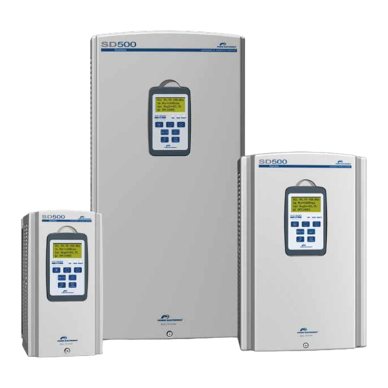
The SD500 low voltage drives by Power Electronics are the ideal frequency converters for the drive of motors from 0.75kW to 90kW. The equipment offers high precision and multiple communication protocols, maximum efficiency and motor care. The SD500 series is an affordable solution for all budget sizes and industry applications. -
Page 14: Configuration Table & Standard Ratings
SD500 POWER ELECTRONICS CONFIGURATION TABLE & STANDARD RATINGS Configuration Table EXAMPLE Code SD5032 2 2 Series SD500 Output Current Rated Current Protection Degree 230VAC IP21 400VAC … … 150A CODIFICATION EXAMPLES: o SD501222 SD500, 12A, 230Vac, Degree of protection IP21. -
Page 15: Standard Ratings At 200Vac - 230Vac (-15% To +10%)
SD5090 2 2 Power ranges for standard 4-pole AC motors (1500rpm) For other configurations, please contact Power Electronics. Check the rated current of the motor plate to ensure compatibility with the chosen frequency inverter. Power Range at 380Vac – 480Vac (-15% to +10%) Operation Temperature 50ºC... -
Page 16: Technical Characteristics
SD500 POWER ELECTRONICS TECHNICAL CHARACTERISTICS Power Range 0.75kW – 90kW Power Supply 200 - 230 Vac (-15% to +10%), 380 - 480Vac (-15% to +10%) Three phase Input Frequency 50 - 60 Hz 5% Input Power Factor >96% C2 classification 0,75 to 22kW... - Page 17 CE, cTick CERTIFICATION [1] For other EMC categories, an optional external filter will be used. For additional information ask Power Electronics. [2] The maximum frequency is 300Hz when selecting the open loop control in the programming parameters. [3] The maximum allowable depends directly on the power of the drive. Consult the SD500 Software and Programming manual for additional information.
-
Page 18: Reception, Handling And Transportation
The SD500 has been carefully tested and packed before delivery. In the event of transport damage, please ensure that you notify the transport agency and Power Electronics: 902 40 20 70 (International +34 96 136 65 57) or your nearest agent, within 24hrs from receipt of the goods. - Page 19 POWER ELECTRONICS SD500 CAUTION Do not load the drives if you suffer from back problems, it could cause damage to the equipment and lead to injury to people. To unpack, open the top part of the box and pull it up to release it.
-
Page 20: Mechanical Installation
SD500 POWER ELECTRONICS MECHANICAL INSTALLATION CAUTION The installation must be done by trained personnel. Otherwise, the equipment can be damaged and/or lead to injury to people. Do not install the drive on a flammable surface during operation. Environmental Ratings It is recommended to follow the instructions of this manual to ensure the correct operation of the drive. -
Page 21: Drive Mounting
The installation method and mounting location must be suitable for the weight and dimensions of the drive. Power Electronics recommends hanging the SD500 cabinet on a solid wall or structure through the anchorages placed on the rear part of the drive, which supports the VFD’s weight and the possible forces generated by the wiring. -
Page 22: Clearances
SD500 POWER ELECTRONICS Clearances The drive should be mounted vertically. Leave enough space (vertically and horizontally) between adjacent drives. DRIVES’ POWER DISTANCE <30kW ≥30kW 100mm 500mm 50mm 200mm Cooling The heat sources inside the equipment correspond with the inverter bridge (IGBTs), rectifier bridge and the input filter. - Page 23 POWER ELECTRONICS SD500 The installer must ensure that the air flows inside the technical room or cabinet, taking into account that hot air cannot be inspired again by the drive. Frame 1 SD500 drives integrate a cooling fan in their bottom part. To replace this fan, push the brackets on the bottom in the direction of the arrow, pull it forward and detach the connector.
- Page 24 SD500 POWER ELECTRONICS Frame 3 and 4 drives integrate a cooling fan in their bottom part. To replace this fan, the user has to unscrew the four screws located in its corners and disconnect the connector. Frame 5 and 6 drives integrate two cooling fans in their top part. To replace these fans, the user has to unscrew the eight screws located in their four corners and disconnect the connectors.
- Page 25 POWER ELECTRONICS SD500 The following tables contain information about efficiency, losses and air flow for all SD500 series drives: Power Calorie Fans Efficiency Frame Code losses losses Flow rate (kcal) SD5005 2 2 96.00 SD5008 2 2 96.00 58,8mᶟ/h 34,6cfm SD5012 2 2 95.00...
-
Page 26: Power Connection
SD500 POWER ELECTRONICS POWER CONNECTION Basic Configuration To install the drive, the additional tools described below may be required. To ensure proper operation of the drive, the supplementary devices must be properly selected and used accordingly. An improper installation or misapplication of the drive can result in a system malfunction, a reduction of the equipment’s life or damage to the equipment’s components. -
Page 27: Topology
For more information, see section 6.5. The SD500 Series rectifier bridge is built in diodes for frames 1 to 4 and in thyristor diodes for frames 5 and 6. In addition, the drives include as standard a harmonic filter that reduces harmonics and improves the power factor by using a DC reactance integrated in the DC bus. - Page 28 SD500 POWER ELECTRONICS The SD500 Series by Power Electronics optionally integrates output dV/dt filters that reduce the dV/dt rise time significantly below 500V/μs - 800V/μs. Furthermore, it reduces the voltage peaks at the motor windings, the common mode currents and the EMC emissions. For more information see sections 6 and...
-
Page 29: Power Terminals Access
POWER ELECTRONICS SD500 Power Terminals Access To access the power terminals of the supply of the drive and the output of the motor, remove the front cover as shown in the next figure. First, remove the display, unscrew the bottom screw, and then unclip the four claps located on both sides of the plastic cover. -
Page 30: Power Terminals Description
SD500 POWER ELECTRONICS Power Terminals Description The power terminals are distributed according to the data shown in the table and figures below. Terminal Description R(L1) Input Supply Voltage Connection S(L2) Three-phase 200 – 230VAC Three-phase 380 – 480VAC T(L3) Ground terminal P(+) Positive Terminal DC BUS –... -
Page 31: Power Connection And Wiring
POWER ELECTRONICS SD500 Power Connection and Wiring Power terminal wiring for Frames 1 to 4 (230Vac & 400Vac) This configuration is valid for the next models: SD500522 to SD509022 (for voltage supply of 230Vac) and SD500242 to SD504542 (for 400Vac) These drives have a built-in braking unit, so it is only necessary to connect the external braking resistor required by the application and depending on the required braking effort. -
Page 32: Wiring And Terminal Section
SD500 POWER ELECTRONICS Wiring and Terminal section Refer to the following table for the wiring terminal sections and screws in the connection of the power input (R, S, T) and output to the motor (U, V, W). Cable**(mm²) Size of the... -
Page 33: Emc Installation Requirements
POWER ELECTRONICS SD500 EMC Installation Requirements Introduction The European EMC Directive defines electromagnetic compatibility as follows: the capability of an apparatus, an industrial plant, or a system to work satisfactorily in the electromagnetic environment without at the same time causing electromagnetic disturbance, which would be unacceptable to apparatus, industrial plant, or systems present in this environment. - Page 34 SD500 POWER ELECTRONICS precedence over all generic or previously applicable product family EMC standards. The PDS in the context of this standard comprises the drive converter, the motor cables and the motor. Therefore, the installer as the ultimate responsible must follow the installation instructions given within this manual.
-
Page 35: Sd500 Compliance
Frames 5 and 6 with filter are always classified as type C3. If another type of classification is required, optional external filters may be used. For additional information, ask Power Electronics. SD500 is not a retail unit, which is neither a plug in device nor a movable device, therefore it must be installed and commissioned by qualified personnel. - Page 36 SD500 POWER ELECTRONICS Deactivation of the EMC filter: As a security measure, check the voltage with a tester 10 minutes after disconnecting the power supply. Remove the connector withdrawing it while holding down the tab. In order to reinstall the connector, make sure that you reinsert the connector with the bridge between the two pins.
-
Page 37: Motor Cable Connection
POWER ELECTRONICS SD500 Activation of the EMC filter In order to activate the EMC filter, the cable must be connected to the upper terminal. When this cable is connected to the lower terminal, the EMC filter will be disarmed. The upper terminal will be a metallic conductor, while the lower one will be isolated. -
Page 38: Dv/Dt Filter (Optional)
SD500 POWER ELECTRONICS dV/dt Filter (Optional) dV/dt filters, installed in the variable speed drives, provide a slower voltage rise time on the motor terminal phase-to-phase voltage, improving the useful life of the motor and avoiding the premature ageing of the motor winding. -
Page 39: Protections
POWER ELECTRONICS SD500 Protections Recommended Circuit Breaker Current data for the circuit breaker (A) DRIVE Thermal Magnetic AC3 Category Protection Protection SD5005 2 2 6,25 11,5 – 13,0 SD5008 2 2 18,4 – 20, 8 SD5012 2 2 27,6 – 31,2 SD5016 2 2 36,8 –... -
Page 40: Recommended Magnetic Contactor
SD500 POWER ELECTRONICS Recommended Magnetic Contactor Drive Power (kW) Current (A) SD5005 2 2 SD5008 2 2 SD5012 2 2 SD5016 2 2 SD5024 2 2 SD5030 2 2 SD5045 2 2 18.5 SD5060 2 2 SD5075 2 2 SD5090 2 2... -
Page 41: Control Connection
To make the connections and to connect the control circuit, use shielded twisted cables, separating the cables from the main power supply. NPN / PNP Configuration Selector The SD500 Series provides two operating modes for the connection of input signals: NPN or PNP. The corresponding connection methods are shown below: CONTROL CONNECTION... - Page 42 SD500 POWER ELECTRONICS NPN mode The drive is configured in this mode when the switch is set to NPN (right position). In this mode, the input terminals are activated using the internal power of the drive. Terminal CM (24Vdc GND) is the common terminal for the input contact signals.
-
Page 43: Tr Jumper Configuration
POWER ELECTRONICS SD500 PNP Mode (external supply) The drive is configured in this mode when the selector is adjusted to PNP (left position). In this mode, the input terminals will activate using a 24Vdc supply, external to the driver, but with the reference terminal attached to the CM terminal of the driver. -
Page 44: I / Ptc Configuration Selector
SD500 POWER ELECTRONICS I / PTC Configuration Selector The SD500 drive uses one of the control terminal inputs as a PTC thermistor input. To configure the analogue current input (AI2 – Terminal I1) as a PTC input, the selector shown in the next figure must be adjusted to the PTC position: There are three possible configurations for the connection of the PTC thermistor depending on how it’s... - Page 45 POWER ELECTRONICS SD500 Group 11 - G11: Protections Start Screen Name / Description Adjust adjust FUNTION DESCRIPTION OPC. G11.23 / Selection of the 23 OvrHtSen= Used in the analogue input 2, motor overtemperature Overheat Sensor setting by current the PTC sensor.
- Page 46 SD500 POWER ELECTRONICS Group 4 – G4: Inputs* ➔ Subgroup 4.1 – S4.1: Digital Inputs Start Screen Name / Description Adjust adjust Sets the digital input as normally open (NO) or normally closed (NC) OPTION FUNCTION G4.1.16 / Selection of...
-
Page 47: Control Terminal Description
POWER ELECTRONICS SD500 Control Terminal Description RECOMMENDED TYPE SYMBOL DESCRIPTION CABLE SELECTION P1 ~ P8 Digital Inputs DI1 to DI8. Function configurable by the user. Digital Common terminal of the digital inputs (Note: In the set of I / O terminals, Inputs CM is different than the common 5G terminal). -
Page 48: Control Terminal Connection Diagram
SD500 POWER ELECTRONICS Control Terminal Connection Diagram The SD500 drive has two groups of connection terminals, which depend on the frame of the drive. There is a set of basic I / O terminals for devices with up to 22kW of capacity (frames 1 to 4) and another set of I / O isolated terminals for devices with a capacity of more than 22kW (frames 5 and 6). - Page 49 POWER ELECTRONICS SD500 Diagram of terminal connections for the basic set of analogue I / O with an analogue bipolar voltage input (0-10Vdc): Note: The control cables must be shielded and grounded. The 5G terminal is different than the CM terminal for frames 1 to 4.
- Page 50 SD500 POWER ELECTRONICS Connection diagram for I / O set of isolated terminals with bipolar voltage analogue input (±10Vdc): Note: The control cables must be shielded and grounded. The 5G terminal will be CM for frames 5 and 6. CONTROL CONNECTION...
- Page 51 POWER ELECTRONICS SD500 Connection diagram for I / O set of isolated terminals with analogue input voltage. Note: The control cables must be shielded and grounded. The 5G terminal will be CM for frames 5 and 6. CONTROL CONNECTION...
-
Page 52: Wiring Recommendations
SD500 POWER ELECTRONICS Wiring Recommendations Before planning the installation, follow the next recommendations. The parallel cable routing should be minimized and the distance between the control wiring and the power wiring should be maximized. It is recommended to route control cables with different voltages in separately cable racks, trays or ducts. -
Page 53: Rs485 Communication
POWER ELECTRONICS SD500 RS485 COMMUNICATION Introduction The drive can be controlled and monitored through a sequence program of a PLC or other master device. Various drives or other slave devices can be connected on an RS485 communication network to be controlled by a PLC or a PC. -
Page 54: Specifications
SD500 POWER ELECTRONICS Specifications General specifications: • Communication Method: RS485. • Transmission Type: Bus Method, Multi-drop Link system. • Applicable to: SD500. • Converter: RS232. • Number of drives: Max. 16 • Transmission distance: Maximum 1,200m (recommended up to 700m). -
Page 55: Starting The Drive On The Communication Network
POWER ELECTRONICS SD500 Parameter Description Setting Communication G20.1.1 0 to 250 Use different numbers in case of installing more than one drive. Address Rs-485 Communication G20.1.2 MODBUS Communication protocol MODBUS-RTU Protocol G20.1.3 Communication Speed 9600bps (Default setting). G20.1.4 Communication Pattern D8 / PN / S1 (Default setting). -
Page 56: Commissioning
SD500 POWER ELECTRONICS COMMISSIONING CAUTION Only qualified personnel are allowed to commission the drive. Read and follow the safety instructions on the first pages of this manual. Neglecting the safety instructions can cause injury or death. Ensure that there is no voltage present in the input power terminals. No voltage should be connected to the drive inadvertently. - Page 57 POWER ELECTRONICS SD500 Connect input power supply. Verify that the display is turned on and set the drive control parameters (Follow the instructions in the Software and Programming manual). Check line voltages with the display. Start the drive without the motor using the display’s keyboard pushbutton “START”.
-
Page 58: Dimensions
SD500 POWER ELECTRONICS DIMENSIONS Dimensions of Frames 1 and 2 FRAME INPUT VOLTAGE DRIVES WEIGHT (kg) 200 - 230VAC (-15% to +10%) SD5005 2 2, SD5008 2 2, SD5012 2 2, SD5016 2 2 380 – 480VAC (-15% to +10%) -
Page 59: Dimensions Of Frames 3 And 4
POWER ELECTRONICS SD500 Dimensions of Frames 3 and 4 FRAME INPUT VOLTAGE DRIVES WEIGHT (Kg) 200 - 230VAC (-15% to +10%) SD5045 2 2, SD5060 2 2 380 – 480VAC (-15% to +10%) SD5024 4 2, SD5030 4 2 200 - 230VAC (-15% to +10%) SD5075 2 2, SD5090 2 2 380 –... -
Page 60: Dimensions Of Frames 5 And 6
SD500 POWER ELECTRONICS Dimensions of Frames 5 and 6 FRAME INPUT VOLTAGE DRIVES WEIGHT (Kg) 200 - 230VAC (-15% to +10%) 380 – 480VAC (-15% to +10%) SD5060 4 2, SD5075 4 2, SD5090 4 2 200 - 230VAC (-15% to +10%) 380 –... -
Page 61: Maintenance
POWER ELECTRONICS SD500 MAINTENANCE The SD500 drives consist of advanced semiconductor devices. Temperature, humidity, vibration and deteriorated components can reduce their efficiency. To avoid any possible irregularity, we recommend making periodic inspections. Warnings Be sure to remove the input power when performing maintenance. - Page 62 SD500 POWER ELECTRONICS Period Instrument of Inspection element Inspection Inspection method Criterion Measurement Are there dust particles? Temperature: Thermometer, Are the ambient temperature -20 to +50 ( or 40ºC) Ambient conditions Visual check Hygrometer, and the humidity within Humidity: below 90% non- Recorder.
-
Page 63: Optional Equipment
POWER ELECTRONICS SD500 OPTIONAL EQUIPMENT Accessories The SD500 Series drive has a wide range of options for different applications. In the image below it can be seen where the additional accessories are connected to the speed drive: CODE ACCESORY DESCRIPTION... -
Page 64: Dynamic Braking Unit
SD500 POWER ELECTRONICS CODE ACCESORY DESCRIPTION Communication speed of 125kbps, 250kbps, 500kbps DeviceNet Bus Topology SD5DN communication Maximum 64 nodes of connecting points module Maximum transmission distance of 500m for 25kbps Communication speed of 78kbps LonWorks Free/bus Topology SD5LW communication... -
Page 65: Dimensions
POWER ELECTRONICS SD500 Dimensions The dynamic braking units correspond with the groups indicated below: Group 1: OPTIONAL EQUIPMENT... -
Page 66: Led Description
SD500 POWER ELECTRONICS Group 2: LED description Group 1: Description Press the switch to release the OCT failure (overcurrent). RESET Pressing this switch turns off the OCT LED. Light son when the braking unit is powered, as it is normally POWER (Green) connected to the drive. -
Page 67: Braking Resistance Terminals
POWER ELECTRONICS SD500 Group 2: Description Lights on when the brake unit is powered (normally connected to POWER (Red) the drive). Lights on when the brake unit is operating properly (due to the RUN (Green) regenerated energy by the motor). -
Page 68: Wiring Diagram
SD500 POWER ELECTRONICS Wiring Diagram The following figure shows the wiring between the drive, the DBU and the braking resistor. * Notes: • In the dynamic braking units of Group 1, the B1 and P terminals are the same. Therefore, the terminal will be connected to the B1 terminal of the braking resistor and to the positive terminal of the drive’s bus. -
Page 69: Dynamic Braking Resistor
3600 Note: The values in this table are based on a 5%, 15 second duty cycle (ED – Enable Duty) of continuous braking. For further information, contact the technical department of Power Electronics. CAUTION Do not touch the braking resistor during operation of the drive as it could be very hot (above 150ºC). -
Page 70: Selecting The External Braking Resistor (Drives With External Brake)
26250 Note: The values in this table are based on a 5%, 15 second duty cycle (ED – Enable Duty) of continuous braking. For further information, contact the technical department of Power Electronics. CAUTION Do not touch the braking resistor during operation of the drive as it could be very hot (above 150ºC). -
Page 71: 400Vac Power Supply
Note: Filters for motor cables of 150m (with shielded cable) and 300m (with unshielded cable [switching freq.: 2kHz]). For more information, please contact Power Electronics. The previous tables describe the dV/dt filters’ code for any SD500 series VSD. These tables are available for every equipment charge condition. -
Page 72: Extension Box
SD500 POWER ELECTRONICS Extension Box FILTER DRIVE FRAME DIMENSIONS REFERENCE REFERENCE SD5002 XX SD5004 XX SD5EB1 SD5006 XX SD5008 XX SD5012 XX SD5EB2 SD5018 XX SD5024 XX SD5EB3 SD5030 XX SD5039 XX SD5EB4 SD5045 XX SD5060 4 2 SD5EB5 SD5075 4 2... -
Page 73: Declaration Of Conformity Ce
www.power-electronics.com CE_SD500_REV.02_14042016... - Page 74 24h Technical Assistance 365 days a year Find your nearest delegation: http://power-electronics.com/contact/ Follow us on:...
Need help?
Do you have a question about the SD500 Series and is the answer not in the manual?
Questions and answers